Download
1 / 60
600 likes | 942 Vues
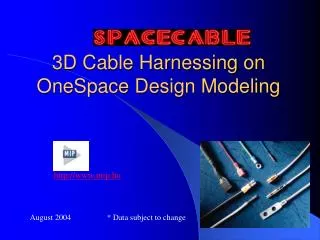
3D Cable Harnessing on OneSpace Design Modeling. http://www.mip.hu. August 2004 * Data subject to change. Introduction to MIP. MIP (Manufacturing Integration Products) founded in 1994, is the general distributor of CoCreate and CIM-TEAM products for Eastern-Europe.

E N D
3D Cable Harnessing on OneSpace Design Modeling http://www.mip.hu August 2004 * Data subject to change
Introduction to MIP • MIP (Manufacturing Integration Products) founded in 1994, is the general distributor of CoCreate and CIM-TEAM products for Eastern-Europe. • With our offices in Hungary, Turkey, Estonia and authorized channel-partners in several Eastern-European countries we are only focused to professional CAD/CAM/PDM products and professional add-on modules for OneSpace products. Last year MIP was able to expand CoCreate sales orders by 58% and increase the number of installed base customers in Eastern-Europe significantly.
SpaceCable features • Different cable types (Incl. flat cables) • Rigid and flexible cabling • Auto-snap connections • Interface to E-CAD systems • Library management • Manufacturing module (with Ver. 2) • User definable bundles with any shape • Manual and Automatic routing (channel routing) • Dynamic cabling • Automatic calculations like wire lengths, channel thicknesses • BOM • PDM integration • Realistic visualization of Harnesses
SpaceCable Terminology • A Harness is a 3D model comprising of routed wires, cables, and bundles in an assembly with all of the related informations. • A Cable is two or more conductors which are contained in the same jacket. • A Wire is a cable with a single conductor. • A Conductor is an internal current carrying entity within a cable. • A Bundle is a group of cables and wires that are sheathed together. • A Jacket is the outer covering of a cable or bundle, that is resistant to environmental hazards and used to protect cable component(s) • A Route is the path that a wire, cable, or bundle follows on an assembly model.
Current phase of development to be continued …
Rigid and Flexible Cables Rigid cables Flexible Cables
AutoSnap Functionality Users can interactively define components and their counterparts by defining mate faces on both components and counterparts.
AutoSnap Functionality … once selected, components automatically “snap” to their counterparts without user interaction
Structures Wires build cables, cables build bundles , bundles build harnesses … • SpaceCable supports different structures • Wires • Cables • Bundles • Channels • Harnesses • …
Structures Special Cable Types • Round • Linear Pattern • Rectangular • Flat • …..
Structures Example: Multi-wire cables 1 – 12 cores
Structures Example: Linear Pattern cables Number of cores free definable in horizontal and vertical directions
Structures Example: User defined Bundles A user defined bundle consists of several round wires and cables with different radii.
Structures Example: User defined Bundles User defined geometry is simply stored as Workplane in a directory together with its bitmap image.Display Table is created automatically at run-time.
Analysis of a harness project • 10 % Administration and preparation of components • 80 % Cable routing • 10 % Post processing and verification
80 % of time needed for routing Biggest potential for efficiency increase ! How to create routing paths efficiently ?
Routing Types • Manual routing On a single face ( planar, cylindrical ) • From face to face ( bend radius ) • From face to ‘space’ • In ‘space’ ( Rigid vs. Flexible cables )Channel routingAuto-routing through predefined channels
Manual Routing Simply click points on a face to define the cable route ...
Manual Routing …go from face to face by simply clicking one point on each face ... 1. point 2. point 3.point
Manual Routing …SpaceCable rolls automatically perpendicular over bothinternal and external edges ...
Manual Routing Move core end point to any point ...
Manual Routing Bring single cores automatically together …
Manual Routing ... use the option ‘Create as single’ ... or re-bundle existing single cables
Manual Routing ... to route multiple cables easy as single cable ...
Manual Routing ... and re-split anytime to route single cores separately SpaceCable ‘remembers’ original structure !
Manual Routing …and can be “splitted” or “bundled” anytime during modelling
Manual Routing …even flat cables can be easily splitted and bundled together!
Channel Routing If you have several parallel cables going in one direction
Channel Routing Define 3D polygonal channels for routing
Channel Routing Modify the channels with simple commands …
Channel Routing … like making parallel to edges
Channel Routing • Select object to be routed (wire.cable or bundle) • Select any 2 points • The shortest path between these pointson the channelis automaticallyfound and the objectis routed.
Channel Routing • Auto-Fillet the object with a simple click
Channel Routing • Put several objects (wires,cables,bundles) into one channel of any complexity.Objects may havedifferent fillet radii.
Dynamic Cabling Cables and wires are modified full dynamically similar to the Dynamic Modeling concept of OneSpace Designer
Interface to E-CAD systems SpaceCable can read and write data from/to any E-CAD systems, which are capable of preparing wire lists in a special ASCII format. After cable and connector data is read, devices are checked for existence and an air-net cabling connection is built automatically from pin to pin. With SpaceCable functionality users can modify air-nets to 3D harnesses.
E-CAD Color Mapping File are simple ASCII files
E-CAD Interface Connectors are placed interactively or automatically
E-CAD Interface SpaceCable checks OSDM model space automatically and finds out which devices are already placed – and which ones user must still load to the model
E-CAD Interface By simply selecting from the “Not Placed” list, users can load and position connectors within one menu.
E-CAD Interface Loaded pkg-parts get automatically new names assigned “Connector_Device name“
E-CAD Interface After all devices are loaded into model space …
E-CAD Interface A straight or tangential airnet connection can be made.