Measuring CDF’s Run II Luminosity
1.05k likes | 1.27k Vues
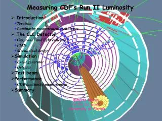
Measuring CDF’s Run II Luminosity. Introduction Tevatron Luminosity measurement techniques The CLC Detector Gas, cones and light collectors PMTs Mechanical design Simulation Event generator Detector Test beam Performance CDF luminosity measurement Summary

Measuring CDF’s Run II Luminosity
E N D
Presentation Transcript
Measuring CDF’s Run II Luminosity • Introduction • Tevatron • Luminosity measurement techniques • The CLC Detector • Gas, cones and light collectors • PMTs • Mechanical design • Simulation • Event generator • Detector • Test beam • Performance • CDF luminosity measurement • Summary Roberto Rossin for the CLC group University of Florida Roberto Rossin Bologna CLC seminar, 03/14/2006
Intro Roberto Rossin Bologna CLC seminar, 03/14/2006
L L Collider Beam Luminosity Instantaneous Luminosity: ~ 2x1032 cm-2s-1 (Run IIa goal) Total Lum: Roberto Rossin Bologna CLC seminar, 03/14/2006
36x36 Bunch Structure Roberto Rossin Bologna CLC seminar, 03/14/2006
Run II Tevatron Luminosity Roberto Rossin Bologna CLC seminar, 03/14/2006
Run II Integrated Luminosity Roberto Rossin Bologna CLC seminar, 03/14/2006
Run II: now and in 2009 Roberto Rossin Bologna CLC seminar, 03/14/2006
Run I Run II m L Luminosity Detector in Run II Operate at: L ~2*1032cm-2sec-1 m ~7ppbar/b.c. • Measure instantaneous and integrated luminosity for CDF and Tevatron • in real-time (~ 1 Hz), standalone, and offline for physics • delivered and live luminosity • bunch by bunch luminosity • keep good precision at high luminosity: < few % • Measure z profile of collisions • Provide a minimum bias trigger for CDF. • Diffractive trigger • NEW: veto for b-physics triggers Roberto Rossin Bologna CLC seminar, 03/14/2006 • Linear, robust, and with many handles for very high Luminosity
Central Muon Central Muon Upgrade Extension Run I beam-beam counters 10o Low Beta Quad Low Beta Quad Silicon Vertex Intermediate Detector Muon System Forward Muon Upgrade Run II plug 3o Low Beta Quad Low Beta Quad Finding room in CDF II Plug Upgrade
Pointing Gas Cherenkov Counters • Sensitive to the right particles! • Much light for particles from interactions • Little light from secondaries and soft particles • Cherenkov thresholds • Shorter paths • Not too sensitive to particles from back (halo) • Excellent amplitude resolution • Count # hits and # particles • No saturation nice linearity • Excellent time resolution • Distinguish # of interactions by time • Robustness • Radiation hard / low mass • Disadvantages: • Needs gas system • New idea, more interesting.... Roberto Rossin Bologna CLC seminar, 03/14/2006
µ= avg. # of interactions/b.c. • f= frequency of bunch crossings • = tot inelastic cross-section • L= inst. luminosity Techniques for Luminosity measurements • Use a good estimator • Measure the fraction of crossings with p-pbar interactions (Run 1 “rate” technique) • Use: prob. of no int. • Direct counting # of p-pbar interactions • Counting particles • Counting time clusters • Cross-calibrate with rarer, clean, better understood process: • Need full understanding of tracking, particle-id, missing-Et,, trigger, NLO, bcknds etc. • Useful for integrated lum abs. normalization • Use a relatively well known, copious, process: • Inclusive inelastic p-pbar cross-section • large acceptance at small angles • Use dedicated detector: Roberto Rossin Bologna CLC seminar, 03/14/2006
Process (mb) CDF meas. @ 1.8 TeV E811 Exp. CDF extrap. @ 2.0 TeV “Soft” Hard Core (no hard scattering) 80.03 (2.24) 71.71 (2.02) 81.90 (2.30) Proton 8% AntiProton 60.33 (1.40)2% 55.92 (1.19) 2% 60.40 (1.40) The total pp cross section + + + + Roberto Rossin Bologna CLC seminar, 03/14/2006
Luminosity methods • Measure energy deposited on CLC Particle counting • Count # of channels above threshold Hit counting (Implemented) • Count empty events Zero counting (main method so far) • Count # of clusters in time Time clusters counting Need to calibrate detector.. estimateea which accounts for limited coverage and efficiency Particle counting Hit counting Zero counting • From simulations • Need all relevant material in CDF • Need “correct” generator… • From real data • W’s, Z's, J/Y 's yields Particle counting with thresholds Roberto Rossin Bologna CLC seminar, 03/14/2006
Particle counting – Hit counting methods Particle Counting Measured at low luminosity from 0-bias data = avg. # particle for a single p-pbar interaction. = measured avg. # particle/bunch crossing “particles” hits Zero bias data Simulation Perfect linearity Hit Counting = avg. # hits for a single p-pbar interaction. = measured avg. # hits/bunch crossing expected L in Run II Roberto Rossin Bologna CLC seminar, 03/14/2006
Particle counting – Hit counting methods Hit Counting Particle Counting • Advantages: • Less sensitive to dgain/gain • Disadvantages • Not linear with physical backgrounds • Saturation @ high L • Advantages: • No saturation @ high L • Linear with physical backgrounds • Disadvantages • dgain/gain= dL/L • Define a collision • { >0 hits in E} .and. { > 0 hits in W} with amplitude > Ao • Online has fixed thresholds • Offline we can normalize to single particle peak (spp) Roberto Rossin Bologna CLC seminar, 03/14/2006
single interaction primaries secondaries 100 p.e. 1 part. five interactions avg. 1 part. 2 part. Luminosity with zero counting method Threshold Zero Counting (empty crossing) Measure the average of the poisson distribution by measuring the 0 bin. An empty crossing is a BC without E–W coincidence in CLC. • Advantages: • Less sensitive to dgain/gain • Formula is correct at every L • Disadvantages • Not linear with physical backgrounds • Statistically limited at very high L Amplitude (p.e.) Roberto Rossin Bologna CLC seminar, 03/14/2006
counter arrival times s=1.4ns ~100ps interaction time Luminosity counting time clusters Measure the number of p-pbar interactions using precise timing Time clusters Roberto Rossin Bologna CLC seminar, 03/14/2006
Detector design Roberto Rossin Bologna CLC seminar, 03/14/2006
= 2.0 n = 3.0 n CDF II cross-section m END WALL HADRON CENTRAL CALORIMETER 2.0 = 1.0 n CAL. 0 30 SOLENOID 1.5 Plug Had. CENTRAL OUTER TRACKER Plug EM 1.0 10o COT Endplate Electronics .5 ISL 3o CLC SVX II 0 2.5 0 .5 1.0 1.5 2.0 3.0 m Z (m)
CLC Mechanical Design 48 counters/side 3 layers with 16 counters each rapidity coverage 3.7<h <4.7 Isob pressure: up to2atm Roberto Rossin Bologna CLC seminar, 03/14/2006
CLC location in CDF Roberto Rossin Bologna CLC seminar, 03/14/2006
CLC Design Roberto Rossin Bologna CLC seminar, 03/14/2006
Cherenkov radiation cosq = 1/( n b ) Npe = No L <sin2q > No = 370 cm-1 eV-1ecol(E)edet(E) dE ecol - light collection efficiency edet- PMT quantum efficiency Pions > 2 GeV & Electrons > ~9 MeV L window particle PMT mylar cone light collector gas Cherenkov Counters – prototype Light emitted if UV dominated Isobutane @ 1atm • n=1.00143 • q =3.1o • sin2q ~ 0.0027 • <ecol>~0.80x0.80 = 0.64 • edet(E) dE ~ 0.84 (quartz window) • No ~ 200 Np.e.~110(L=200cm) Roberto Rossin Bologna CLC seminar, 03/14/2006
Gas & cones • Gas: Isobutane at low (< 2atm) pressure • Higher pressure: • higher refraction index higher amount of light • higher Cherenkov angle more reflections • Cones • Aluminized mylar: • 2 x 0.1 millimiters thick • 60 nm aluminum layer • MgF2 coated • reflectivity for Cherenkov light > 90% Roberto Rossin Bologna CLC seminar, 03/14/2006
Light collector (Al) Aluminized Mylar cones - design 50 nm Al + 50 nm MgF2 (rad hard) 2 layers; 0.1 mm each; 60 nm Al coating cone cap Roberto Rossin Bologna CLC seminar, 03/14/2006
Light collectors • Light collectors • Used to collect light onto the face of the PMT • Aluminum with conical shape • optimized for maximum light collection efficiency • inner: single cone • middle & outer: bi-cone (10° and 14°). For large collectors bi-cone has higher efficiency and uniformity. Give a less divergent light beam • Polished to optical quality; coated with 50 nm Al and 50 nm MgF2. • Gap between collector and PMT window allow to hide PMT deep inside magnetic shield. • L/D > 1 in order to protect PMT against the magnetic field (L=distance between shield edge and PMT, D=shield diameter) Roberto Rossin Bologna CLC seminar, 03/14/2006
Light collection efficiency simulation Cone+coll efficiency VS collector-PMT gap Cone eff VS photon position Collector eff: bi-cone single cone Collector efficiency VS photon angle Total eff: bi-cone single cone gap = 0, 5, 10, 15 mm Roberto Rossin Bologna CLC seminar, 03/14/2006
PMT PMT choice • Geometrical constraints • ~ 25 mm diameter (all layers…) • Larger doesn’t fit • Smaller requires large angle collector (losses) • Performance • Quartz window • UV transparent • Rad hard • Thin • Less light • Better timing resolution • Timing resolution • Sub 100 ps resolution R5800Q Hamamatsu 10-stage / 106 gain 0.8 mm concave-convex quartz window 25 mm x 60 mm 1.7 ns rise-time ~12 ns pulse width Roberto Rossin Bologna CLC seminar, 03/14/2006
Gas System CLC systems Roberto Rossin Bologna CLC seminar, 03/14/2006
Luminosity Readout & Information Flow CLLD CLLD OFFLINE ONLINE
white Tyvec quartz fibers Calibration system • Green-blue bright LED from Ledtronics • Quartz fiber + Tyvec reflector • Pulse generator @ 8 V x ~40 nsec duration • 100-500 mV signal for gain calibrations • About 600 psec r.m.s. signal • Use peak for initial timing calibration Roberto Rossin Bologna CLC seminar, 03/14/2006
Full detector simulation Roberto Rossin Bologna CLC seminar, 03/14/2006
Simulation: event generator • ppbar processes: • elastic scattering (pp pp) • diffractive scattering (pp pX,pX,X1,X2) • "hard core" scattering (pp X) • for luminosity only inelastic • Event generators: • MBR • Pythia • both have been tuned to the CDF data • typical multiplicity in one ppbar primary interaction is 5 particles per unit of h. • luminous region has gaussian shape in z and t. Roberto Rossin Bologna CLC seminar, 03/14/2006
Simulation: CDF detector and CLC • CDF detector simulation based on Geant 4 • simulation accounts for all secondary particles with energy > 5MeV • total number of particles detected is considerable larger than the primary ones • ~50% from IP • 25% from beam pipe • 25% from plug calorimeter • Gas counter simulation • light yield accounts for: • the geometrical path • the reflectivity (90%) • threshold of the Cherenkov radiation. • d-electron are below thr. Roberto Rossin Bologna CLC seminar, 03/14/2006
all secondaries primaries gth=20 g factor Cherenkov p threshold electr. ~ 8 MeV pions ~ 2 GeV momentum (GeV) Simulation: Momentum Threshold • Simulation accounts for the momentum threshold • for isobutane at 1atm threshold is for g = 19 • 2.6 GeV pions • 9.5 MeV electrons • distribution almost flat at g ~ 20: • 10% pressure change = • 4% gth change = • 0.8% N particles Roberto Rossin Bologna CLC seminar, 03/14/2006
All particles All secondaries Secondaries from plug Particles from PV Simulation: amplitude distribution • Simulated amplitude for 5 pp interactions. • primary particles • single and double particle peaks • particle counting can be performed • secondaries still have low amplitude • Simulated amplitude for particles from minimum bias pp interactions. • primary particles • 100 p.e. peak • low amplitude tail due to parallax • secondaries have low amplitude • 50 p.e. threshold cuts: • 84% secondaries • 23% of primaries Roberto Rossin Bologna CLC seminar, 03/14/2006
Fraction of particles that hit window light yield set to 26p.e./mm window thickness = 5mm Overall effects: peak width increased by 20% peak shift: 111 p.e. 115 p.e. Electrons contribution mayor contribution to secondaries electrons produced on beampipe give large signal PMT window & electrons all particles hit window electrons Roberto Rossin Bologna CLC seminar, 03/14/2006
Detector performance Roberto Rossin Bologna CLC seminar, 03/14/2006
First collisions • First collisions at 1.96 TeV at CDF seen by Cherenkov Luminosity Counters in October 2nd 2000 • 1 proton bunch vs 4 anti-proton bunches • 19 ns separation between anti-proton bunches Roberto Rossin Bologna CLC seminar, 03/14/2006
Beam structure: timing Losses Time (ns) 396 ns Collisions main bunch Collisions satellite bunch + losses Time (ns) Time (ns) Roberto Rossin Bologna CLC seminar, 03/14/2006
P-pbar interactions Z position From CLC timing information determine Z position of collisions • Was VERY useful during Tevatron commissioning: • CLC was the only detector which could measure position of interactions during that time • Helped a lot to AD to tune the machine Roberto Rossin Bologna CLC seminar, 03/14/2006
CLC amplitude distribution • Single Particle Peak (spp) • Higher CLC occupancy due to more material close to beam • SPP clearly seen after isolation cat useful for calibration • Great agreement with simulation amplitude, spp units Simulation (dots) East module (blue) West module (red) amplitude, spp units Roberto Rossin Bologna CLC seminar, 03/14/2006
T0 Calibration • Calibration using p and pbar beams WEST WEST Time offset w.r.t. a reference channel (before applying T0 correction) Time offset w.r.t. a reference channel (after applying T0 correction) EAST EAST Roberto Rossin Bologna CLC seminar, 03/14/2006
Luminosity Measurements Roberto Rossin Bologna CLC seminar, 03/14/2006
Luminosity with zero counting method Zero counting (empty crossing) Measure the average of the poisson distribution by measuring the 0 bin. An empty crossing is a BC without E–W coincidence in CLC. In an ideal world (…acc=4p and e=100%) …But life is tough e0 = probability of NO hits on both modules eE/W = probability of hits only on East/West module Provided by Monte Carlo e0 7% eE/W 12% Roberto Rossin Bologna CLC seminar, 03/14/2006
Empty crossing method Hit Counting Empty crossings D0 Roberto Rossin Bologna CLC seminar, 03/14/2006
Real Time Luminosity Delivered Inst. Lum CDF live Inst. Lum Proton losses Abort gap losses Roberto Rossin Bologna CLC seminar, 03/14/2006
Instantaneous Total Instantaneous Total Bunch by Bunch L Tevatron delivered CDF live Roberto Rossin Bologna CLC seminar, 03/14/2006
Wln Xsecs & Z ll Xsec Measured with 194 pb-1 Roberto Rossin Bologna CLC seminar, 03/14/2006
Wen yield versus luminosity Data collected from Jun 23 to Jul 3 2004 Roberto Rossin Bologna CLC seminar, 03/14/2006