Advanced Camera Positioning Techniques in C-Frame Systems
110 likes | 212 Vues
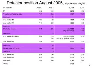
Comprehensive guide covering camera positions, mask installation conventions, shelves adjustment methods and lens specifications in C-Frame systems. Includes detailed instructions for precise setup and alignment.

Advanced Camera Positioning Techniques in C-Frame Systems
E N D
Presentation Transcript
y=0 beam RASNIK position on C-frame 6050/2=3025 the edge of C-Frame 340(S2) 172(S3) 60 C-Frame 83 200 285 1.25 240 90 60 600 440 pillar 100 y=-2925 100 100 30 90 90 101.25 680 cable goes out from mask horizontally ( not rotated by 120º ) x=+33.4 x=0 x=-56.6 x=+134.6 x=+224.6 left right
y=0 beam CCD on shelves the edge of C-Frame C-Frame 240 90 60 101.25 pillar 90 90 100 y=-2925 100 100 22 270 45 45 Cameras for C-frame 1st pillar 1 2 2nd pillar 3 4 2nd pillar 5 6 • Cameras for C-frame • 1 1 2 2-nd shelf • 3 3 4 2-nd shelf • 6 5 5 6 3-rd shelf 3
STATION 3 C-FRAME PLANE 6 STATION 1 C-FRAME PLANE 1 STATION 1 C-FRAME PLANE 2 STATION 3 C-FRAME PLANE 5 SHORT SHORT SHORT SHORT LONG LONG LONG LONG Z AXIS (BEAM) INSIDE PICTURE LENS CRYOGENICS OT1 STATION 2 C-FRAME PLANE 3 STATION 2 C-FRAME PLANE 4 OT2 H I - 340um MASK, HOLDER BEHIND C-FRAME SHORT SHORT LONG LONG B - 340um MASK- HOLDER BEHIND C-FRAME E - 30um MASK + long H. +lens on the same C-FRAME F - 85um MASK+short H. +lens on the same C-FRAME DX - 340um MASK, reversed holder IN FRONT OF C-FRAME DV - 120um MASK, reversed holder IN FRONT OF C-FRAME OT3 4
convention for masks installation on table level - top view RICH2 - 340µm mask Outer Outer Inner Long C-Frame - 120µm mask Short C-Frame 3600 -5 - 30 / 85µm mask + lens +5 3410 ~185 - reversed holders H3 B3 H3 B3 6 6 T3-Q13-VX T3-Q02-VX T3-Q13-XU T3-Q02-XU 5 5 2nd right pillar 2nd left pillar 4 4 I2 T2-Q13-VX T2-Q02-VX B2 T2-Q13-XU T2-Q02-XU 3 3 D D H1 B1 2 2 T1-Q13-VX T1-Q02-VX 1 1 T1-Q13-XU T1-Q02-XU F E 1st right pillar 1st left pillar Z +224.6 +134.6 +33.4 X -56.6 5 H13 B123D EFI2– lens type magnet
Shelves This picture for 2nd pillars BEAM IS TILTED, use shelves with identical thickness => No up-down symmetry in choice of holes for 2nd & 3rd station, Upper raw for 2nd station, Lower raw for 3rd station. 6
Shelves on 1st pillar Use identical, short shelves => up-down symmetry, lines only in outside raw. Shelves are adjustable in x and y by +/- 10mm 7
Fixing shelf in the middle bottom vs OT2 or OT3 Lines lengthened by reversing mask holder and lens holder C – to see full 9*9 segment on any mask D – to increase depth of focus CCD adjustable in z with range 40 Lens fixed 200 OT 5th C-Frame OT 6th C-Frame IT 15+e 21 (C,D) 28 +5 D Z +5 C b line of sight in IT a 0 A (A,B) 10 0 B mask 43 Z 100 120 shelf 14 -3025 -2987 adjustable in x & y 115 level of table surface -3140= -6300+2400+760 153 10 75 8 220 190/220
lens + mask’s holder on C-frames – OT1 OT 1st C-Frame OT 2nd C-Frame ADJUSTMENT +- 5 END OF MASK AT END OF ENVELOPE STOP 6 44 21 44 6 32 A=38or 27 4,5 44 16 A=27 A=38 32+4,5 +-5 or 21+4,5 +-5 ENVELOPE 100 9
Two lines measure displacement of the bridge in horizontal directions x & z with precision of a few microns vertical (y1mm) not used LONG VERTICAL LINES TO THE BRIDGE CCD 6.7m lens 1.7m+margins2m mask y z x
Tool for adjustingshelftoC-frame y x C-frame stop mechanism ON • This toolhelps: • make runners on shelf perpendicular to one C-frame • (in x-z plane and in y-z plane) • 2) adjust (in x and in y)shelf to hole in one C-frame |(2ndC-frame)-(far end of 1st new middle shelf)|-5= =501500 y First install cylinder z Then adjust shelf versus cylinder for every shelf on nearest C-frame in hole without mask holder side view Pillar (on sides) front view 11