METAL CASTING
METAL CASTING. NITC. Some basics - you had in Foundry. Sand casting. Steps: 1.Mechanical Drawing of the part 2. Making pattern- about pattern material. 3.Making cores- if needed 4.Preparing drag and cope. (Setting the core, positioning etc.) 5.Removal of pattern


METAL CASTING
E N D
Presentation Transcript
METAL CASTING NITC
Some basics - you had in Foundry Sand casting. Steps: • 1.Mechanical Drawing of the part • 2. Making pattern- about pattern material. • 3.Making cores- if needed • 4.Preparing drag and cope. (Setting the core, positioning etc.) • 5.Removal of pattern • 6Assembling cope and drag • 7.Pouring- factors, method, etc. • 8.Casting removed • 9.Trimming etc. • 10. READY FOR SHIPMENT NITC
Some basics you had in Foundry 1.Mechanical Drawing of the part2. Making pattern- about pattern material.3.Making cores- if needed4.Preparing drag and cope. (Setting the core, positioning etc.)5.Removal of pattern6Assembling cope and drag7.Pouring- factors, method, etc.8.Casting removed9.Trimming etc.10. READY FOR SHIPMENT 3 1 2 3a 3c 3b 4b 5a 4a 5b 6 8&9 10
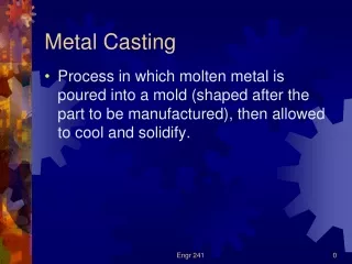
CASTING FUNDAMENTALS Basically involves i. Pouring molten metalinto a mould patterned after the part to be made WITHOUT TURBULANCE , SERIES OF EVENTS TAKES PLACE INFLUENCE SIZE, SHAPE, UNIFORMITY OF THE GRAINS FORMED, AND THUS THE OVERALL PROPERTIES. • ii. Allow it to cool HEAT TRANSFER DURING SOLIDIFICATION • iii. Remove from the moldINFLUENCE OF THE TYPE OF MOULD MATERIAL SIMILARITY WITH POURING CAKE MIX INTO A PAN NITC
POURING CAKE MIX INTO A PAN (MOULD) & BAKING IT*SELECT THE KIND AND SIZE OF PAN, *CONTROL THE COMPOSITION OF THE MIX, * CAREFULLY POUR THE MIX, * SET THE PROPER BAKING TEMPERATURE, * SET THE TIMER FOR PROPER BAKING TIME, * LEAVE THE CAKE IN THE MOULD FOR A CERTAIN AMOUNT OF TIME BEFORE REMOVING.(CASTING OF PLASTICS & CERAMICS - DIFFERENT) NITC
Knowledge of certain fundamental relationships is essential to produce good quality economic castingsThis knowledge helps in establishing proper techniques for mould design and casting practice.Castings must be free from defects, must meet the required strength, dimensional accuracy, surface finish NITC
- pattern making - Core making - Gating system Outline of production steps in a typical sand casting operation Moulding Mould Sand Melting Pouring casting Heat Treat Clean Inspect Furnaces Solidification Shakeout Addl. Heat Treatment Defects, pressure tightness, dimensions NITC
ADVANTAGES OF CASTING PROCESS • Process is cheap • More suitable for mass production • Most suitable for manufacturing complex/complicated/intricate shaped products. • Large parts weighing several tonnes and also small components weighing a few grams can be cast. • No limitation on the size of component. • Directional properties absent in castings. Components with uniform properties as well as with varying properties at different locations can be cast. • By use of cores, saving in machining of holes achieved. • Internal stresses are relieved during solidification in many types of castings. • Even some materials which cannot be made by other processes made by casting: eg. Phosphor-Bronze. NIT CALICUT NITC
DISADVANTAGES • Cast product properties inferior in many cases when compared with other manufacturing processes. • Elevated temperature working in castings, as material has to be melted. • Thin section limitations exist. • For number of components very small, casting not preferred. NIT CALICUT NITC
SIGNIFICANT FACTORS- • TYPE OF METAL, • THERMAL PROPERTIES OF BOTH THE METAL AND MOULD, • GEOMETRIC RELATIONSHIP BETWEEN THE VOLUME AND SURFACE AREA ,AND • SHAPE OF MOULD. NITC
SOLIDIFICATION OF METALS • AFTER POURING MOLTEN METAL INTO MOULD, SERIES OF EVENTS TAKES PLACE DURING SOLIDIFICATION AND COOLING TO AMBIENT TEMPERATURE. • THESE EVENTS GREATLY INFLUENCE THE SIZE, SHAPE, UNIFORMITY OF THE GRAINS FORMED, AND THUS THE OVERALLL PROPERTIES. NITC
Three Stages of Contraction (Shrinkage) The liquid Metal has a Volume"A”It solidifies to solid with a new volume "B"The solidified casting further contracts (shrinks) through the cooling process to Volume "C"
COOLING CURVE For pure metal or compound TEMPERATURE Cooling of Liquid Latent heat of solidification given off during freezing- At constant temperature Freezing begins Freezing ends Liquid + Solid Cooling of solid Liquid Solid TIME, log scale
And FOR ALLOYS: Alloys solidify over a range of temperatures Begins when temp. drops below liquidous, completed when it reaches solidous. Within this temperature range, mushy or pasty state. Inner zone can be extended throughout by adding a catalyst.- sodium, bismuth, tellurium, Mg (or by eliminating thermal gradient, i.e. eliminating convection. (Expts in space to see the effect of lack of gravity in eliminating convection) (refresh dendritic growth- branches of tree, interlock, each dendrite develops uniform composition, etc) COOLING CURVE TEMPERATURE Freezing with drop in temperature For Binary solid solutions TIME, log scale
* The ambient temperature is always in a state of transition Minor variations in volumetric displacement are negligible, compared to the variations that occur from "A" to "B" and lastly to "C". A B C * A B C
STRUCTURE FOR PURE METALS: At the mould walls, metal cools rapidly. Produces solidified skin or shell (thickness depends on composition, mould temperature, mould size and shape etc) • These of equiaxed structure. • Grains grow opposite to heat transfer through the mould • These are columnar grains • Driving force of the heat transfer is reduced away from the mould walls and blocking at the axis prevents further growth NITC
Solidified structures of metal - solidified in a square mould (a). Pure metal (b). Solid solution (c). When thermal gradient is absent within solidifying metal • Development of a preferred texture • - for pure metal at a cool mould wall. • A chill zone close to the wall and • then a columnar zone away from the mould. Three basic types of cast structures- (a). Columnar dendritic; (b). equiaxed dendritic; (c). equiaxed nondendritic
Size and distribution of the overall grain structure throughout a casting depends on rate & direction of heat flow(Grain size influences strength, ductility, properties along different directions etc.)CONVECTION- TEMPERATURE GRADIENTS DUE TO DIFFERNCES IN THE DENSITY OF MOLTEN METAL AT DIFFERENT TEMPERATURES WITHIN THE FLUID - STRONGLY EFFECTS THE GRAIN SIZE. Outer chill zones do not occur in the absence of convection NITC
Atm.Pressure Pouring basin MOULD SPRUE GATE LIKE A PRESSURISED SYSTEM
MOULDING BOARDFLASKSHOWELDRAW SPIKERIDDLESLICKRAMMERLIFTERSTRIKE-OFF BARTROWELS GATE CUTTER BELLOWSSPRUE PINS VENT ROD ….. MOULDERS’ TOOLS AND EQUIPMENT
a b c d e Making a Core; (a). Ramming Core Sand. (b). Drawing the core box (c). Baking in an oven (d) Pasting the core halves (e). Washing the core with refractory slurry
1 3a • Make the pattern in pieces, prepare the core. • Position the drag half of pattern on mould board in the drag half of flask • Prepare the drag half of mould, roll drag over, apply parting sand, place the cope half of pattern and flask, ram and strike off excess sand • Separate flasks, remove patterns, cut sprue, set core in place, close flask • Now after clamping, ready fro pouring. 2 4a 3b 4b 5
Design of Risers and Feeding of Castings • A simplified diagram by putting in references to the equations (1, 2 & 4) there is no Equation 3, diagram not changed • EQ(1) - Freeze Point Ratio (FPR) FPR=X X = (Casting Surface/Casting Volume) / (Riser Surface/Riser Volume) • EQ(2) - Volume Ratio (VR) (Y Axis) VR=Y=Riser Vol/Casting Vol* Note: The riser volume is the actual poured volume • EQ(4) - (Freeze Point Ratio) Steel • X=0.12/y-0.05 + 1.0* • *The constants are from experiments and are empirical References - AFS Text Chapter 16; Chastain's Foundry manual Vol 2, Google
Volumes, Surface Areas, Castings and Risers... There are relationships between all these items and values that will help in designing a complete mold that controls progressive solidification, and influences directional solidification to produce castings with minimal porosity and shrinkage defects. This is by ensuring that the riser(s) are the last to solidify.
4 points about the Riser/Casting Relationship • 1 - Risers are attached to the heaviest sections of the casting • 2 - Risers are the last to solidify • 3 - A casting that has more than one heavy section requires at least one riser per heavy section • 4 - Occasionally the thermal gradient is modified at the mold-metal interface by the introduction of a "Chill" that can better conduct the heat away from the casting and lower the solidification time for that section.
Gating / Runner Design • Now a look at the flow characteristics of the metal as it enters the mold and how it fills the casting. Of the flow characteristics fluidity/viscosity plays a role. Also, • velocity, • gravitational acceleration & vortex, • pressure zones, • molten alloy aspiration from the mold and • the momentum or kinetic energy of a fluid.
The demarcation point is Re < 2000 is considered a Laminar Flow Re > 2000 is considered a Turbulent Flow Objective is to maintain Re below 2000.
Basic Components of a Gating System • The basic components of a gating system are: • Pouring Basin, • Sprue, • Runners and • Gates that feed the casting. The metal flows through the system in this order. Some simple diagrams to be familiar with are:
Pouring Basin - This is the "Crucible -Mold Interface", A pouring cup and pouring basin are not equivalents, The pouring cup is simply a larger target when pouring out of the crucible, a Pouring Basin has several components that aid in creating a laminar flow of clean metal into the sprue.The basin acts as a point for the liquid metal to enter the gating system in a laminar fashion. "Crucible-Mold Interface" is where the metal from the crucible first contacts the mold surface. This area is lower than where the Mouth of the Sprue is located, by having a pool of metal from the flow will be less chaotic than pouring from the crucible down into the sprue."Dross-Dam" - to skim or hold back any dross from the crucible or what accumulated through the act of pouring. As the lower portion fills and the metal is skimmed, the clean(er) metal will rise up to meet the opening of the sprue in a more controlled fashion.
Sprue Placement and Parts The sprue is the extension of the sprue mouth into the mold The choke or narrowest point in the taper is the point that would sustain a "Head" or pressure of molten metal. To reduce turbulence and promote Laminar Flow, from the Pouring Basin, the flow begins a near vertical incline that is acted upon by gravity and with an accelerative gravity force that is 32ft/Sec/Sec So a mass falling has a velocity of 384 inches/sec after a free fall duration of 1 entire second. Fluids in free fall tend to distort from a columnar shape at their start into an intertwined series of flow lines that have a rotational vector or vortex effect (Clockwise in the northern hemi-sphere, and counter clockwise in the southern hemi-sphere)...
The rotational effect, though not a strong force, is causing the cork-screwing effect of the falling fluid. If allowed to act on the fluid over a great enough duration or free fall the centrifugal force will separate the flow into droplets. • None of the above promotes Laminar flow, plus it aids the formation of dross and gas pick-up in the stream that is going to feed the casting.
Some dimensioning ratio's from Chastain's Foundry Manual (no.2) • By creating a sprue with a taper, the fluid is constrained to retain it's shape, reducing excessive surface area development (dross-forming property) and gas pick-up. • The area below the sprue is the "Well". The well reduces the velocity of the fluid flow and acts as a reservoir for the runners and gates as they fill. • 1- Choke or sprue base area is 1/5th the area of the well. • 2- The well depth is twice the runner depth. • 3- the Runner is positioned above the midpoint of the well's depth
The Runner System • The runner system is fed by the well and is the path that the gates are fed from. • This path should be "Balanced" with the model of heating or AC ductwork serving as a good illustration. The Runner path should promote smooth laminar flow by a balanced volumetric flow, and avoiding sharp or abrupt changes in direction. • The "Runner Extension" is a "Dead-End" that is placed after the last gate. The R-Ext acts as a cushion to absorb the forward momentum or kinetic energy of the fluid flow. The R-Ext also acts as a "Dross/Gas Trap" for any materials generated and picked-up along the flow of the runner. • An Ideal Runner is also proportioned such that it maintains a constant volumetric flow through virtually any cross-sectional area. In the illustration, notice that the runner becomes proportionally shallower at the point where an in-gate creates an alternate path for the liquid flow.
The Gating System • The Gates (in this case) accommodate a directional change in the fluid flow and deliver the metal to the Casting cavity. • Again, the design objective is to promote laminar flow, the primary causes of turbulence are sharp corners, or un-proportioned gate/runner sizes. • The 2 (two) dashed blue areas when added together form a relationship to the dashed blue area of the Runner, which forms a relationship to the Choke or base of the Sprue Area.
The issue of sharp corners (both inner and outer) create turbulence, low & high pressure zones that promote aspiration of mold gases into the flow, and can draw mold material (sand) into the flow. None of this is good... By providing curved radius changes in direction the above effects are still at play but at a reduced level. Sharp angles impact the solidification process and may inhibit "Directional Solidification" with cross-sectional freezing... • The image to the right is just too good a representation to pass-up.. • By proportioning the gating system, a more uniform flow is promoted with near equal volumes of metal entering the mold from all points. In an un-proportioned system the furthest gates would feed the most metal, while the gates closest to the sprue would feed the least. (this is counter to what one initially thinks).
Formulae, Ratios and Design Equations • What is covered so far is comprehensive, and intuitive on a conceptual level, but the math below hopefully offers some insight into quick approximations for simple designs, and more in-depth calculations for complex systems. • Computerized Flow Analysis programs are used extensively in large Foundry operations. • From basic concepts, designing on a state of the art system shall be attempted: • Continuity Equation – • This formula allows calculation of cross-sectional areas, relative to flow Velocity and Volumetric flow over unit time. This is with the assumption that the fluid flow is a liquid that does NOT compress (that applies to all molten metals).
Here, a flow passes through A1 (1" by 1", 1 sq") The passage narrows to a cross-sectional area A2 (.75" by .75", 0.5625 sq") The passage expands to a cross-sectional area A3 (1" by 1", 1 sq"). Q= Rate of Flow (Constant - uncompressible) V=Velocity of flow A=Area (Cross-section) If A1 and A2 are considered, the Area A2 is almost half of A1, thus the velocity at A2 has to be almost double of A1.
GATING RATIO is- Areas of Choke : Runner : Gate(s) • The base of the Sprue and Choke are the same. • The ratios between the cross-sectional Area can be grouped into either Pressurized or Unpressurized. • Pressurized: A system where the gate and runner cross-sectional areas are either equal or less than the choke cross-sectional area.
A1= Choke = 1 Sq Inch • A2 = 1st Runner c/s Area = 0.75 Sq Inch • A3 = 2nd Runner c/s Area = 0.66 Sq Inch • A4 = 1st Gate = 0.33 Sq inch • A5 = 2nd Gate = 0.33 Sq Inch • Areas A2 & A3 do not get added as they are positioned in line with each other and flow is successive between the points and not simultaneous. • While Areas A4 & A5 are added together as flow does pass through these points simultaneously. • This example would resolve to a pressurized flow of 1 : 0.75 : 0.66
Unpressurized: • The key distinction is that the Runner must have a cross sectional area greater than the Choke, and it would appear that the Gate(s) would equal or be larger than the Runner(s). • Common Ratio's noted in Chastian's Vol 2 are: • 1 : 2 : 4 • 1 : 3 : 3 • 1 : 4 : 4 • 1 : 4 : 6
An exception is noted in Chastain with a 1 : 8 : 6 ratio to promote dross capture in the runner system of Aero-Space castings. • The Continuity Equation is simplified with the use of ratios as the velocity is inversely proportional between any 2 adjacent ratio values. ie H : L equates to an increase in velocity while a L : H equates to a drop in velocity. • Laminar Flow is harder to control at a high velocity than a relatively lower velocity. • Chastain's Vol 2 has much more mathematical expressions and calculations.
PURE METALS- Have clearly defined melting/freezing point, solidifies at a constant temperature. Eg: Al - 6600C, Fe - 15370C, and W- 34100C. NITC
Solidified structures of metal - solidified in a square mould (a). Pure metal (b). Solid solution (c). When thermal gradient is absent within solidifying metal • Development of a preferred texture • - at a cool mould wall. • A chill zone close to the wall and • then a columnar zone away from the mould. Three basic types of cast structures- (a). Columnar dendritic; (b). equiaxed dendritic; (c). equiaxed nondendritic
STRUCTURE FOR PURE METALS: At the mould walls, metal cools rapidly. Produces solidified skin or shell(thickness depends on composition, mould temperature, mould size and shape etc) • These are of equiaxed structure. • Grains grow opposite to heat transfer through the mould • These are columnar grains • Driving force of the heat transfer is reduced away from the mould walls and blocking at the axis prevents further growth NITC
Size and distribution of the overall grain structure throughout a casting depends on rate & direction of heat flow(Grain size influences strength, ductility, properties along different directions etc.)CONVECTION- TEMPERATURE GRADIENTS DUE TO DIFFERNCES IN THE DENSITY OF MOLTEN METAL AT DIFFERENT TEMPERATURES WITHIN THE FLUID - STRONGLY EFFECTS THE GRAIN SIZE. Outer chill zones do not occur in the absence of convection NITC
FOR ALLOYS: • Alloys solidify over a range of temperatures • Begins when temp. drops below liquidous, completed when it reaches solidous. • Within this temperature range, mushy or pasty state (Structure as in figure) • Inner zone can be extended throughout by adding a catalyst.- sodium, bismuth, tellurium, Mg (or by eliminating thermal gradient, i.e. eliminating convection. (Expts in space to see the effect of lack of gravity in eliminating convection) (refresh dendritic growth- branches of tree, interlock, each dendrite develops uniform composition, etc) NITC
SOLIDIFICATION TIMEDuring solidification, thin solidified skin begins to form at the cool mould walls. Thickness increases with time.For flat mould walls thickness time (time doubled, thickness by 1.414) NITC
CHVORINOV’S RULEsolidification time (t) is a function of volume of the casting and its surface areat = C ( volume/ surface area )2C is a constant [depends on mould material, metal properties including latent heat, temperature]A large sphere solidifies and cools at a much slower rate than a small diameter sphere. (Eg- potatoes, one big and other small) Volume cube of diameter of sphere, surface area square of diameter NITC