
Soft x-rays Advanced Light Source
E N D
Presentation Transcript
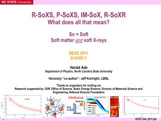
R-SoXS, P-SoXS, IM-SoX, R-SoXR What does all that mean?So = SoftSoft matter and soft X-raysREXS 20116/16/2011Harald AdeDepartment of Physics, North Carolina State UniversityHonorary “co-author”: Jeff Kortright, LBNLThanks to organizers for inviting meResearch supported by: DOE Office of Science, Basic Energy Science, Division of Materials Science and Engineering, National Science Foundation
Soft x-rays Advanced Light Source
Beamlines we use are: 5.3.2.2 (STXM), 6,3.2 (SoXR), 7.3.3. (WAXS), 11.0.1.2 (SoXS), 11.0.2.1 (STXM) Hongping at 7.3.3. (SAXS/WAXS) Cheng and Hongping at 11.0.1.2. (R-SoXS) Brian at 5.3.2.2 STXM 11.0.2.1 STXM Our energy range is lower than what you have seen so far at this conference 3
scattering vector q (mm-1) scattering vector q (mm-1) Small Angle Scattering/RSoXS Coherence length larger than domains, but smaller than illuminated area Structure/morphology Determination in Reciprocal Space: Resonant X-ray Scattering 40 information about domain statistics 20 0 -20 -40 -40 -20 0 20 40 Structure/morphology Determination in Real Space: Absorption X-ray Microscopy Best for NEXAFS Relatively slow Low damage Figure courtesy of/after J. Stohr
Goals of presentation • Convey the power of carbon K-edge R-SoXS • Focus on organic devices • Provide understanding of some of the underlying physics of the tools • “gear heads” tutorial light • This will be short, you are already experts • Turn a few of you into (more frequent?) soft X-ray users • Impossible task? study organics at the carbon (or nitrogen and oxygen) edge great potential and opportunity to develop a new user community
Highlights/roadmap C. Wang, T. Araki, H. Ade Appl. Phys. Lett. 87, 214109 (2005) G. E. Mitchell, et al., Appl. Phys. Lett. 89, 044101 (2006); T. Araki et al. Appl. Phys. Lett. 89, 124106 (2006) • Feasibility is established Development of a new facility at the ALS dedicated to R-SoXS H. Yang, et al. AdvFunct Mater. 20, 4209 (2010) • X-ray reflectivity coupled to device data and MC simulations shows that interface structure in PFB/F8BT bilayers contributes 50% to the poor performance. Non-equilibrium, sharp interfaces are best S. Swaraj et al., Nano Letters 10, 6863 (2010) • Scattering and microscopy shows that domains in all-polymer blends are too large or too impure Need better control. Use of block copolymers!?
282.4 eV, calculations Si Si Highlights/roadmap-II: work in progress X-ray reflectivity on organic TFT devices: • N2200/dielectric • pBTTT/dielectric Polarization dependent Soft X-ray Scattering (P-SoXS) • Unique contrast mechanism. How can it be exploited? Index matched Soft X-ray scattering (IM-SoXS) • Turn top surface “off” • Diffuse scatting from buried polymer interface • Eliot Gann will give a talk in ~1.5 hours
Soft X-rays: Unique interaction with organic materials Scattering factorsand optical constants of C,N, and O Assumed density of 1 g/cm3 Complex index of refraction: n=1-δ+iβ “Natural” scattering contrast: Assumed density of 1 g/cm3 • Quantitative absorption microscopy: • Beer’s Law: I=I0e-μρt • 20-200 nm thick samples
Near Edge X-ray Absorption Fine Structure (NEXAFS) Spectroscopy “Resonant effects” are more than just elemental Unsaturation C=O Unoccupied Molecular Orbital e- Unsaturation C=C C 1s edge ~ 290 eV N 1s edge ~ 405 eV O 1s edge ~ 540 eV hn Photon energy
MDI polyurea PBMA MDI polyurethane PMMA TDI polyurea TDI polyurethane Nylon-6 PEO PS EPR PBrS PP SAN PE Spectroscopy = selective contrast Dhez, Ade, and Urquhart J. Electron Spectrosc. 128, 85 (2003) vectra PC PAR Kevlar™ Data: Stony Brook STXM at NSLS PBT PNI PET Fingerpt.ppt 8 May 1998
PS N P2VP PMMA Resonant Scattering/ReflectivityR-SoXS/R-SoXR(contrast is almost as good as selective deuteration) Absorption (NEXAFS) Scattering factors f’ and f” (optical const. δ and β, respectively) show strong energy dependence Neutron community use different terminology: complex scattering length Dispersion R or I (Δδ2+Δβ2) • “Bond specific” scattering! • Substantial potential as complementary tool!
NC STATEUniversity air PS PMMA Si Ade Research Group (Polymer Physics/X-ray Characterization Techniques) Soft X-ray Resonant ReflectivityPS/PMMA bilayer Complementary Tool to Neutrons and hard X-rays C. Wang, T. Araki, H. Ade Appl. Phys. Lett. 87, 214109 (2005) • Observed strong photon energy dependence Potential: Diffuse scattering from interfaces Data: Araki, BL6.3.2. ALS, Berkeley
air PS PMMA Si Reflectivity: If we had perfect data (simulations) PS 50nm/PMMA 200nm
Momentum transfer: PS PMMA Si Interpretation of Reflectivity Data
NC STATEUniversity (Figure courtesy J. Stubbs UNH) 280.0 eV 280.0 eV 285.2 eV 285.2 eV 288.4 eV 288.4 eV 320.0 eV 320.0 eV qR=4.5 q=0.39 qR=7.73 q=0.68 qR=10.9 q=0.95 Scattering Intensity [a.u] R=115 nm q (1/nm) Ade Research Group (Polymer Physics/X-ray Characterization Techniques) PMMA/P(BA-co-S) P(MA-b-MMA) / PS J.M. Stubbs, D.C. Sundberg Polymer 46 (2005) 1125 Different process and composition • Fuzzy TEM • modified core/shell structure? • Phase less separated? • Where really is the PS? Idealized, “consensus” particle “PS” “PS” “PS”-”shell” 200 nm 150 nm Scattering Intensity [a.u] 100 nm • “PS” about same size than PMMA/acrylate! • Scattering indicates PS is slightly more in center of nanoparticle relative to PMMA/P(BA-co-S) q (1/nm) • “PS” effective radius larger than PMMA “radius” T. Araki et al. Appl. Phys. Lett. 89, 124106 (2006)
Organic Electronics: An interesting area of applications and characterization needsContext: Energy Security/Independence, Global Warming Flexible organic light emitting diodes (OLED) (from Sony) organic photovoltaics (OPV) (from Nicole Cappello, Gatech) organic thin film transistors, (from www. livescience.com.)
PCBM P3HT Critical Factors in Organic Photovoltaic Devices:Morphology, interfaces, domain purity, and energy levels Bulk heterojunction devices Need lateral structure ~10 nm in size Light “Organic Photovoltaics: Materials, Device Physics, and Manufacturing Technologies”, Wiley-VCH (August 25, 2008) • What makes fullerene-based devices so successful? • What are the primary shortcomings of polymer-polymer devices and can they be overcome? • What role can soft x-ray characterization methods play? • Morphology (including crystallinity): scattering and microscopy • Interfaces: scattering and reflectivity • Purity: quantitative compositional microscopy and scattering
Donor 1:1 PFB:F8BT blend all-polymer solar cell model system 140 nm cast from chloroform smallest domains to date140 °C yields max in efficiency, but PCE still <2% Lateral composition maps from x-ray microscopy Acceptor NEXAFS contrast • Effective resolution < film thickness • Need 3D resolution, i.e. tomography • or scattering C. R. McNeill et al. Nanotechnology 19, 424015 (2008)
Transmission geometry Channeltron Sample q q X-rays Resonant Soft X-ray Scattering (R-SoXS) of PFB:F8BT blendHigh enough scattering contrast for transmission experiment S. Swaraj,C. Wang, H Yan, B Watts,J. Lüning, C. R. McNeill, and H. Ade, Nano Letters 10, 6863 (2010)
Domain size analysis with R-SoXS1:1 PFB:F8BT blends cast from chloroform Pair distribution function P(r) R-SoXS 284.7 eV Small domains disappear at 200 ºC Small domains get more pure ~7 nm feature Average domain much larger than exciton diffusion length and/or too impure poor efficiency (partially) explained Good S/R and Information content to 1 nm-1 S. Swaraj,C. Wang, H Yan, B Watts,J. Lüning, C. R. McNeill, and H. Ade, Nano Letters 10, 6863 (2010)
Another all-polymer blend: P3HT:F8TBTInitial data/analysis PCE=1.8% at 140 °C McNeill APL 90, 193506 (2007) Unfavorable large range of domain size once annealed
Organic Thin Film TransistorsInterfacesIn-plane organization
Interfaces in OTFTs:dielectric/N2200 We are in the process to measure buried interface structure of N2200 with different dielectric polymers Relate this to device performance Interface with PMMA is exceptionally sharp: Initial fit ~0.5 nm PS is less sharp: Initial fit ~0.8 nm) Cytop even less sharp: Initial fit ~1,0 nm Correlated to turn-on voltage PMMA/N2200 285.8 eV PS/N2200 284.1 eV cytop/N2200 688 eV H. Yan, Z. Gu, H. Ade (NCSU), C.R. McNeill. T. Schuettfort (Cambridge)
Polarization in STXM and ScatteringAnother interesting and unique contrast mechanism probing domain size and domain correlation in TFT applications
Specific molecular orbitals are probed via x-ray photons at resonant energies Absorption enhanced if photon polarization is parallel to transition dipole moment Polarization contrast in STXM and Scattering Collins et al. (2011).
390 eV 285.4 eV Scattering is sensitive to quasi-domain size of pentaceneP-SoXS proof of principle 293eV • Use scattering when domains are too small for STXM • Or scattering too weak in TEM 500nm
As-cast Transmission P-SoXS from PBTTT/PMMA TFTs: I(q)·q2 • Non-Resonant scattering sensitive to mass-thickness • Similar to scattering using hard x-rays • Resonant scattering profiles completely different, showing definite trend • Clear trend of both feature size and feature contrast Annealed Thickness/roughness/density Domain correlations Non-Resonant 250 eV Resonant 285.4 eV 780nm 600nm 480nm max~150nm Feature Size ~ Position of Max Collins, Yan, Gann, Cochran, Chabinyc, Wang, McNeil, Ade (2011).
Device mobility is directly related to domain size • saturation mobilities correlate exponentially to quasi-domain size • Corr. Coef = 0.992 Collins, Yan, Gann, Cochran, Chabinyc, Wang, McNeil, Ade (2011).
~150 nm thick, annealed at 180C P-SoXS signal from P3HT:F8TBT blends STXM image at 285.4 eV Not sure yet what this all means, Better real space method would be really helpful Collins, Yan, Gann, Cochran, Chabinyc, Wang, McNeil, Ade (2011).
Utility of Soft X-rays • Lots of great science possible (It’s also fun!) • R-SoXS, P-SoXS has the potential to reach a large, new community • Need more facilities, • particularly one in Europe • Better analysis tools
R-SoXS, R-SoXR, P-SoXS, IM-SoXSWhat do the acronyms mean?So = SoftSoft matter and soft X-raysR-SoXS: Resonant Soft X-ray ScatteringR-SoXR: Resonant Soft X-ray ReflectivityP-SoXS: Polarization dependent R-SoXSIM-SoXS: Index Matched SoXS SoXS rhymes with
Thank you for your attentionThanks to members of my group:B. Collins, S. Swaraj (now Soleil), H. Yan, E. Gann, J. Seokand C. McNeill, N. Greenham, I. Hwang (Cambridge), C. Wang (ALS), M. Chabinyc, and J. Cochran (UCSB) Financial support: DOE Office of Science, Basic Energy Science, Division of Materials Science and Engineering Contract: DE-FG02-98ER45737 Cheng and Hongping at the ALS