MSK Transmitter
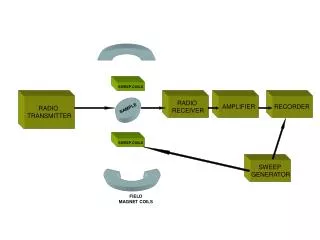
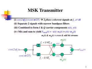
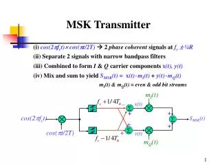
m I (t). _ +. x(t). S MSK (t). + +. y(t). m Q (t). . + +. cos(2 f c t ). . . cos( t/2T ). MSK Transmitter. (i) cos(2 f c t ) cos( t/2T ) 2 phase coherent signals at f c ¼R (ii) Separate 2 signals with narrow bandpass filters

MSK Transmitter
E N D
Presentation Transcript
mI(t) _ + x(t) SMSK(t) + + y(t) mQ(t) + + cos(2fct) cos(t/2T) MSK Transmitter (i) cos(2fct)cos(t/2T) 2 phase coherent signals atfc ¼R (ii) Separate 2 signals with narrow bandpass filters (iii) Combined to formI & Q carrier components x(t), y(t) (iv) Mix and sum to yield SMSK(t) = x(t)mI(t) + y(t)mQ(t) mI(t) & mQ(t) = even & odd bit streams
Coherent MSK Receiver • (i) SMSK(t) split & multiplied by locally generated • x(t) & y(t) (I & Q carriers) • (ii) mixer outputs are integrated over 2T & dumped • (iii) integrate & dump output fed to decision circuit every 2T • input signal level compared to threshold decide 1 or 0 • output data streams correspond to mI(t) & mQ(t) • mI(t) & mQ(t) are offset & combined to obtain demodulated signal • *assumes ideal channel – no noise, interference
SMSK(t) Coherent MSK Receiver Threshold Device mI(t) t = 2(k+1)T x(t) y(t) Threshold Device mQ(t) t = 2(k+1)T
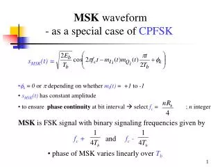
Gaussian MSK • Gaussian pulse shaping to MSK • smoothens phase trajectory of MSK signal • over time, stabilizes instantaneous frequency variations • results in significant additional reduction of • sidelobe levels • GMSK detection can be coherent (like MSK) • or noncoherent (like FSK)
Gaussian MSK • premodulation pulse shaping filter used to filter NRZ data • - converts full response message signal into partial response scheme • full response baseband symbols occupy Tb • partial responsetransmitted symbols span several Tb • - pulse shaping doesn’t cause pattern’s averaged phase trajectory to deviate from simple MSK trajectory
Gaussian MSK • GMSKs main advantages are • power efficiency - from constant envelope (non-linear amplifiers) • excellent spectral efficiency • pre-modulation filtering introduces ISI into transmitted signal • if B3dbTb > 0.5 degradation is not severe • B3dB= 3dB bandwidth of Gaussian Pulse Shaping Filter • Tb= bit duration = baseband symbol duration • irreducible BER caused by partial response signaling is the • cost for spectral efficiency & constant envelope • GMSK filter can be completely defined from B3dB Tb • - customary to define GMSK by B3dBTb
Impulse responseof pre-modulation Gaussian filter : hG(t) = transfer function of pre-modulation Gaussian Filter is given by HG(f) = is related toB3dB by = Gaussian MSK
Impact of B3dBTb • (i) ReducingB3dBTb : spectrum becomes more compact (spectral efficiency) • causes sidelobes of GMSK to fall off rapidly • B3dBTb = 0.5 2nd lobe peak is 30dB below main lobe • MSK 2nd peak lobe is 20dB below main lobe • MSK GMSK with B3dBTb = • (ii) increases irreducible error rate (IER)due to ISI • ISI degradation caused by pulse shaping increases • however - mobile channels induce IER due to mobile’s velocity • if GMSK IER < mobile channel IER no penalty for using GMSK
0 -10 -20 -30 -40 -50 -60 BTb = (MSK) BTb = 1.0 BTb = 0.5 BTb = 0.2 0 0.5 1.0 1.5 2.0 (f-fc)T PSD of GMSK signals • Increasing BTb • reduces signal spectrum • results in temporal spreading and distortion
RF bandwidth containing % power as fraction of Rb e.g. for BT = 0.2 99% of the power is in the bandwidth of 1.22Rb • [Ish81] BER degradation from ISI caused by GMSK filtering is • minimal at B3dBTb= 0.5887 • degradation in required Eb/N0 = 0.14dB compared to case of no ISI
Pe = BER of GMSK for AWGN channel • [Mur81] shown to perform within 1dB of optimal MSK with B3dBTb = 0.25 • since pulse shaping causes ISI Peis function of B3dBTb Pe= bit error probability is constant related to B3dBTb • B3dBTb = 0.25 = 0.68 • B3dBTb = = 0.85 (MSK)
Gaussian LPF FM Transmitter RF GMSK Output NRZ bits GMSK Transmitter Block Diagram GMSK Transmitter • (i) pass mNRZ(t) through Gaussian base band filter (see figure below) • - mNRZ(t) = NRZ bit stream • output of Gaussian filter passed to FM modulator • used in digital implementation for • - Global System for Mobile (GSM) • - US Cellular Digital Packet Data (CDPD) • (ii) alternate approach is to use standard I/Q modulator
demodulated signal /2 modulated IF input signal loop filter Q IF LO I /2 clock recovery • GMSK Receiver • RF GMSK signal can be detected using • (i) orthogonal coherent detectors (block diagram) • (ii) simple non-coherent detectors (e.g. standard FM discriminators) (i) GMSK Receiver Block Diagram-orthogonal coherent detectors
carrier recovery using De Budas method for(similar to Costas loop) • S’(t) = output of frequency doubler that contains 2 discrete frequency • components • - divide S’(t) by four: S’(t) /4 • - equivalent to PLL with frequency doubler
D Q C D Q C D Q C D Q C modulated IF input signal D Q C clock recovery demodulated signal D C Q loop filter VCO • De Budasmethod implemented using digital logic • 2 D flip flops (DFF) act as quadrature product demodulator • XORs act as based band multipliers • mutually orthogonal reference carriers generated using 2 DFFs • VCOcenter frequency set to 4 fc ( fc = carrier center frequency) Logic Circuit for GMSK demodulation
Detecting GMSK signal by sampling output of FM demodulator is a non-optimal, effective method • e.g. • Assume 0.25GMSK: B3dbTb= 0.25 & Rb = 270kbps • then • Tb = Rb-1= 3.7us • B3dB = 0.25/Tb = 67.567kHz • Occupied Spectrum - 90% power 0.57Rb = 153.9kHz • - use table