Download
1 / 78

E N D
IRAM and ISTORE Projects Aaron Brown, James Beck, Rich Fromm, Joe Gebis, Paul Harvey, Adam Janin, Dave Judd, Kimberly Keeton, Christoforos Kozyrakis, David Martin, Rich Martin, Thinh Nguyen, David Oppenheimer, Steve Pope, Randi Thomas, Noah Treuhaft, Sam Williams, John Kubiatowicz, Kathy Yelick, and David Patterson http://iram.cs.berkeley.edu/[istore] Fall 2000 DIS DARPA Meeting
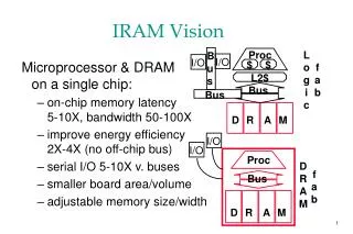
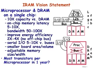
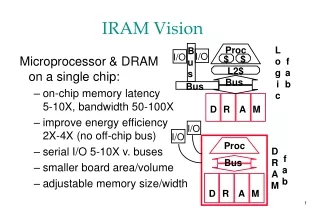
IRAM and ISTORE Vision • Integrated processor in memory provides efficient access to high memory bandwidth • Two “Post-PC” applications: • IRAM: Single chip system for embedded and portable applications • Target media processing (speech, images, video, audio) • ISTORE: Building block when combined with disk for storage and retrieval servers • Up to 10K nodes in one rack • Non-IRAM prototype addresses key scaling issues: availability, manageability, evolution Photo from Itsy, Inc.
Data Cache (8KB) IRAM Overview • A processor architecture for embedded/portable systems running media applications • Based on media processing and embedded DRAM • Simple, scalable, energy and area efficient • Good compiler target Flag 0 Flag 1 Instr Cache (8KB) FPU Flag Register File (512B) MIPS64™ 5Kc Core CP IF Arith 0 Arith 1 256b 256b SysAD IF Vector Register File (8KB) 64b 64b Memory Unit TLB 256b JTAG IF DMA Memory Crossbar … JTAG DRAM0 (2MB) DRAM1 (2MB) DRAM7 (2MB)
Architecture Details • MIPS64™ 5Kc core (200 MHz) • Single-issue scalar core with 8 Kbyte I&D caches • Vector unit (200 MHz) • 8 KByte register file (32 64b elements per register) • 256b datapaths, can be subdivided into 16b, 32b, 64b: • 2 arithmetic (1 FP, single), 2 flag processing • Memory unit • 4 address generators for strided/indexed accesses • Main memory system • 8 2-MByte DRAM macros • 25ns random access time, 7.5ns page access time • Crossbar interconnect • 12.8 GBytes/s peak bandwidth per direction (load/store) • Off-chip interface • 2 channel DMA engine and 64n SysAD bus
14.5 mm 20.0 mm Floorplan • Technology: IBM SA-27E • 0.18mm CMOS, 6 metal layers • 290 mm2 die area • 225 mm2 for memory/logic • Transistor count: ~150M • Power supply • 1.2V for logic, 1.8V for DRAM • Typical power consumption: 2.0 W • 0.5 W (scalar) + 1.0 W (vector) + 0.2 W (DRAM) + 0.3 W (misc) • Peak vector performance • 1.6/3.2/6.4 Gops wo. multiply-add (64b/32b/16b operations) • 3.2/6.4 /12.8 Gops w. madd • 1.6 Gflops (single-precision) • Tape-out planned for March ‘01
“VIRAM-8MB” 4 lanes, 8 Mbytes 190 mm2 3.2 Gops at 200 MHz(32-bit ops) Alternative Floorplans “VIRAM-2Lanes” 2 lanes, 4 Mbytes 120 mm2 1.6 Gops at 200 MHz “VIRAM-Lite” 1 lane, 2 Mbytes 60 mm2 0.8 Gops at 200 MHz
VIRAM Compiler • Based on the Cray’s production compiler • Challenges: • narrow data types and scalar/vector memory consistency • Advantages relative to media-extensions: • powerful addressing modes and ISA independent of datapath width Frontends Optimizer Code Generators C T3D/T3E Cray’s PDGCS C++ C90/T90/SV1 Fortran95 SV2/VIRAM
Exploiting 0n-Chip Bandwidth • Vector ISA uses high bandwidth to mask latency • Compiled matrix-vector multiplication: 2 Flops/element • Easy compilation problem; stresses memory bandwidth • Compare to 304 Mflops (64-bit) for Power3 (hand-coded) • Performance scales with number of lanes up to 4 • Need more memory banks than default DRAM macro for 8 lanes
Compiling Media Kernels on IRAM • The compiler generates code for narrow data widths, e.g., 16-bit integer • Compilation model is simple, more scalable (across generations) than MMX, VIS, etc. • Strided and indexed loads/stores simpler than pack/unpack • Maximum vector length is longer than datapath width (256 bits); all lane scalings done with single executable
Vector Vs. SIMD: Example • Simple image processing example: • conversion from RGB to YUV Y = [( 9798*R + 19235*G + 3736*B) / 32768] U = [(-4784*R - 9437*G + 4221*B) / 32768] + 128 V = [(20218*R – 16941*G – 3277*B) / 32768] + 128
VIRAM Code (22 instructions) RGBtoYUV: vlds.u.b r_v, r_addr, stride3, addr_inc # load R vlds.u.b g_v, g_addr, stride3, addr_inc # load G vlds.u.b b_v, b_addr, stride3, addr_inc # load B xlmul.u.sv o1_v, t0_s, r_v # calculate Y xlmadd.u.sv o1_v, t1_s, g_v xlmadd.u.sv o1_v, t2_s, b_v vsra.vs o1_v, o1_v, s_s xlmul.u.sv o2_v, t3_s, r_v # calculate U xlmadd.u.sv o2_v, t4_s, g_v xlmadd.u.sv o2_v, t5_s, b_v vsra.vs o2_v, o2_v, s_s vadd.sv o2_v, a_s, o2_v xlmul.u.sv o3_v, t6_s, r_v # calculate V xlmadd.u.sv o3_v, t7_s, g_v xlmadd.u.sv o3_v, t8_s, b_v vsra.vs o3_v, o3_v, s_s vadd.sv o3_v, a_s, o3_v vsts.b o1_v, y_addr, stride3, addr_inc # store Y vsts.b o2_v, u_addr, stride3, addr_inc # store U vsts.b o3_v, v_addr, stride3, addr_inc # store V subu pix_s,pix_s, len_s bnez pix_s, RGBtoYUV
RGBtoYUV: movq mm1, [eax] pxor mm6, mm6 movq mm0, mm1 psrlq mm1, 16 punpcklbw mm0, ZEROS movq mm7, mm1 punpcklbw mm1, ZEROS movq mm2, mm0 pmaddwd mm0, YR0GR movq mm3, mm1 pmaddwd mm1, YBG0B movq mm4, mm2 pmaddwd mm2, UR0GR movq mm5, mm3 pmaddwd mm3, UBG0B punpckhbw mm7, mm6; pmaddwd mm4, VR0GR paddd mm0, mm1 pmaddwd mm5, VBG0B movq mm1, 8[eax] paddd mm2, mm3 movq mm6, mm1 paddd mm4, mm5 movq mm5, mm1 psllq mm1, 32 paddd mm1, mm7 punpckhbw mm6, ZEROS movq mm3, mm1 pmaddwd mm1, YR0GR movq mm7, mm5 pmaddwd mm5, YBG0B psrad mm0, 15 movq TEMP0, mm6 movq mm6, mm3 pmaddwd mm6, UR0GR psrad mm2, 15 paddd mm1, mm5 movq mm5, mm7 pmaddwd mm7, UBG0B psrad mm1, 15 pmaddwd mm3, VR0GR packssdw mm0, mm1 pmaddwd mm5, VBG0B psrad mm4, 15 movq mm1, 16[eax] MMX Code (part 1)
paddd mm6, mm7 movq mm7, mm1 psrad mm6, 15 paddd mm3, mm5 psllq mm7, 16 movq mm5, mm7 psrad mm3, 15 movq TEMPY, mm0 packssdw mm2, mm6 movq mm0, TEMP0 punpcklbw mm7, ZEROS movq mm6, mm0 movq TEMPU, mm2 psrlq mm0, 32 paddw mm7, mm0 movq mm2, mm6 pmaddwd mm2, YR0GR movq mm0, mm7 pmaddwd mm7, YBG0B packssdw mm4, mm3 add eax, 24 add edx, 8 movq TEMPV, mm4 movq mm4, mm6 pmaddwd mm6, UR0GR movq mm3, mm0 pmaddwd mm0, UBG0B paddd mm2, mm7 pmaddwd mm4, pxor mm7, mm7 pmaddwd mm3, VBG0B punpckhbw mm1, paddd mm0, mm6 movq mm6, mm1 pmaddwd mm6, YBG0B punpckhbw mm5, movq mm7, mm5 paddd mm3, mm4 pmaddwd mm5, YR0GR movq mm4, mm1 pmaddwd mm4, UBG0B psrad mm0, 15 paddd mm0, OFFSETW psrad mm2, 15 paddd mm6, mm5 movq mm5, mm7 MMX Code (part 2)
pmaddwd mm7, UR0GR psrad mm3, 15 pmaddwd mm1, VBG0B psrad mm6, 15 paddd mm4, OFFSETD packssdw mm2, mm6 pmaddwd mm5, VR0GR paddd mm7, mm4 psrad mm7, 15 movq mm6, TEMPY packssdw mm0, mm7 movq mm4, TEMPU packuswb mm6, mm2 movq mm7, OFFSETB paddd mm1, mm5 paddw mm4, mm7 psrad mm1, 15 movq [ebx], mm6 packuswb mm4, movq mm5, TEMPV packssdw mm3, mm4 paddw mm5, mm7 paddw mm3, mm7 movq [ecx], mm4 packuswb mm5, mm3 add ebx, 8 add ecx, 8 movq [edx], mm5 dec edi jnz RGBtoYUV MMX Code (pt. 3: 121 instructions)
IRAM Status • Chip • ISA has not changed significantly in over a year • Verilog complete, except SRAM for scalar cache • Testing framework in place • Compiler • Backend code generation complete • Continued performance improvements, especially for narrow data widths • Application & Benchmarks • Handcoded kernels better than MMX,VIS, gp DSPs • DCT, FFT, MVM, convolution, image composition,… • Compiled kernels demonstrate ISA advantages • MVM, sparse MVM, decrypt, image composition,… • Full applications: H263 encoding (done), speech (underway)
Scaling to 10K Processors • IRAM + micro-disk offer huge scaling opportunities • Still many hard system problems (AME) • Availability • systems should continue to meet quality of service goals despite hardware and software failures • Maintainability • systems should require only minimal ongoing human administration, regardless of scale or complexity • Evolutionary Growth • systems should evolve gracefully in terms of performance, maintainability, and availability as they are grown/upgraded/expanded • These are problems at today’s scales, and will only get worse as systems grow
VAX crashes ‘85, ‘93 [Murp95]; extrap. to ‘01 • HW/OS 70% in ‘85 to 28% in ‘93. In ‘01, 10%? Is Maintenance the Key? • Rule of Thumb: Maintenance 10X HW • so over 5 year product life, ~ 95% of cost is maintenance
Hardware Techniques for AME • Cluster of Storage Oriented Nodes (SON) • Scalable, tolerates partial failures, automatic redundancy • Heavily instrumented hardware • Sensors for temp, vibration, humidity, power, intrusion • Independent diagnostic processor on each node • Remote control of power; collects environmental data for • Diagnostic processors connected via independent network • On-demand network partitioning/isolation • Allows testing, repair of online system • Managed by diagnostic processor • Built-in fault injection capabilities • Used for hardware introspection • Important for AME benchmarking
Storage-Oriented Node “Brick” Portable PC CPU: Pentium II/266 + DRAM Redundant NICs (4 100 Mb/s links) Diagnostic Processor • ISTORE Chassis • 80 nodes, 8 per tray • 2 levels of switches: • 20 100 Mb/s • 2 1 Gb/s • Environment Monitoring: • UPS, redundant PS, • fans, heat and vibration sensors... Disk Half-height canister ISTORE-1 system Hardware: plug-and-play intelligent devices with self-monitoring, diagnostics, and fault injection hardware • intelligence used to collect and filter monitoring data • diagnostics and fault injection enhance robustness • networked to create a scalable shared-nothing cluster Scheduled for 4Q 00
Brick shelf Brick shelf Brick shelf Brick shelf Brick shelf Brick shelf Brick shelf Brick shelf Brick shelf Brick shelf Patch panel Patch panel Patch panel Patch panel ISTORE-1 System Layout PE1000s PE1000s: PowerEngines 100Mb switches PE5200s: PowerEngines 1 Gb switches UPSs: “used” PE5200 PE5200 UPS UPS UPS UPS UPS UPS
ISTORE Brick Node Block Diagram Mobile Pentium II Module SCSI North Bridge CPU Disk (18 GB) South Bridge Diagnostic Net DUAL UART DRAM 256 MB Super I/O Monitor & Control Diagnostic Processor BIOS Ethernets 4x100 Mb/s PCI • Sensors for heat and vibration • Control over power to individual nodes Flash RTC RAM
ISTORE Brick Node • Pentium-II/266MHz • 256 MB DRAM • 18 GB SCSI (or IDE) disk • 4x100Mb Ethernet • m68k diagnostic processor & CAN diagnostic network • Packaged in standard half-height RAID array canister
Software Techniques • Reactive introspection • “Mining” available system data • Proactive introspection • Isolation + fault insertion => test recovery code • Semantic redundancy • Use of coding and application-specific checkpoints • Self-Scrubbing data structures • Check (and repair?) complex distributed structures • Load adaptation for performance faults • Dynamic load balancing for “regular” computations • Benchmarking • Define quantitative evaluations for AME
Network Redundancy • Each brick node has 4 100Mb ethernets • TCP striping used for performance • Demonstration on 2-node prototype using 3 links • When a link fails, packets on that link are dropped • Nodes detect failures using independent pings • More scalable approach being developed Mb/s
Load Balancing for Performance Faults • Failure is not always a discrete property • Some fraction of components may fail • Some components may perform poorly • Graph shows effect of “Graduated Declustering” on cluster I/O with disk performance faults
Availability benchmarks • Goal: quantify variation in QoS as fault events occur • Leverage existing performance benchmarks • to generate fair workloads • to measure & trace quality of service metrics • Use fault injection to compromise system • Results are most accessible graphically
Example: Faults in Software RAID • Compares Linux and Solaris reconstruction • Linux:minimal performance impact but longer window of vulnerability to second fault • Solaris: large perf. impact but restores redundancy fast Linux Solaris
Towards Manageability Benchmarks • Goal is to gain experience with a small piece of the problem • can we measure the time and learning-curve costs for one task? • Task: handling disk failure in RAID system • includes detection and repair • Same test systems as availability case study • Windows 2000/IIS, Linux/Apache, Solaris/Apache • Five test subjects and fixed training session • (Too small to draw statistical conclusions)
Sample results: time • Graphs plot human time, excluding wait time
Analysis of time results • Rapid convergence across all OSs/subjects • despite high initial variability • final plateau defines “minimum” time for task • plateau invariant over individuals/approaches • Clear differences in plateaus between OSs • Solaris < Windows < Linux • note: statistically dubious conclusion given sample size!
ISTORE Status • ISTORE Hardware • All 80 Nodes (boards) manufactured • PCB backplane: in layout • Finish 80 node system: December 2000 • Software • 2-node system running -- boots OS • Diagnostic Processor SW and device driver done • Network striping done; fault adaptation ongoing • Load balancing for performance heterogeneity done • Benchmarking • Availability benchmark example complete • Initial maintainability benchmark complete, revised strategy underway
BACKUP SLIDES IRAM
Vector Reg. Elements Vector Reg. Elements Vector Reg. Elements Vector Reg. Elements Integer Datapath 0 Integer Datapath 1 Integer Datapath 0 Integer Datapath 1 Integer Datapath 0 Integer Datapath 1 Integer Datapath 1 Integer Datapath 0 FP Datapath FP Datapath FP Datapath FP Datapath Flag Reg. Elements & Datapaths Flag Reg. Elements & Datapaths Flag Reg. Elements & Datapaths Flag Reg. Elements & Datapaths Xbar IF Xbar IF Xbar IF Xbar IF 64b 64b 64b 64b Modular Vector Unit Design • Single 64b “lane” design replicated 4 times • Reduces design and testing time • Provides a simple scaling model (up or down) without major control or datapath redesign • Lane scaling independent of DRAM scaling • Most instructions require only intra-lane interconnect • Tolerance to interconnect delay scaling 256b Control
Base-line system comparison • All numbers in cycles/pixel • MMX and VIS results assume all data in L1 cache
Virtual Processors ($vlr) VP0 VP1 VP$vlr-1 vr0 General Purpose Registers (32) vr1 vr31 $vpw vf0 Scalar Regs Flag Registers (32) vf1 vs0 vs1 vf31 1b vs15 64b Vector Architecture State
Vector Instruction Set • Complete load-store vector instruction set • Uses the MIPS64™ ISA coprocessor 2 opcode space • Ideas work with any core CPU: Arm, PowerPC, ... • Architecture state • 32 general-purpose vector registers • 32 vector flag registers • Data types supported in vectors: • 64b, 32b, 16b (and 8b) • 91 arithmetic and memory instructions • Not specified by the ISA • Maximum vector register length • Functional unit datapath width
Compiler/OS Enhancements • Compiler support • Conditional execution of vector instruction • Using the vector flag registers • Support for software speculation of load operations • Operating system support • MMU-based virtual memory • Restartable arithmetic exceptions • Valid and dirty bits for vector registers • Tracking of maximum vector length used
BACKUP SLIDES ISTORE
ISTORE: A server for the PostPC Era Aaron Brown, Dave Martin, David Oppenheimer, Noah Trauhaft, Dave Patterson,Katherine Yelick University of California at Berkeley Patterson@cs.berkeley.edu UC Berkeley ISTORE Group istore-group@cs.berkeley.edu August 2000
ISTORE as Storage System of the Future • Availability, Maintainability, and Evolutionary growth key challenges for storage systems • Maintenance Cost ~ >10X Purchase Cost per year, • Even 2X purchase cost for 1/2 maintenance cost wins • AME improvement enables even larger systems • ISTORE also cost-performance advantages • Better space, power/cooling costs ($@colocation site) • More MIPS, cheaper MIPS, no bus bottlenecks • Compression reduces network $, encryption protects • Single interconnect, supports evolution of technology, single network technology to maintain/understand • Match to future software storage services • Future storage service software target clusters
Lampson: Systems Challenges • Systems that work • Meeting their specs • Always available • Adapting to changing environment • Evolving while they run • Made from unreliable components • Growing without practical limit • Credible simulations or analysis • Writing good specs • Testing • Performance • Understanding when it doesn’t matter “Computer Systems Research-Past and Future” Keynote address, 17th SOSP, Dec. 1999 Butler Lampson Microsoft
Jim Gray: Trouble-Free Systems • Manager • Sets goals • Sets policy • Sets budget • System does the rest. • Everyone is a CIO (Chief Information Officer) • Build a system • used by millions of people each day • Administered and managed by a ½ time person. • On hardware fault, order replacement part • On overload, order additional equipment • Upgrade hardware and software automatically. “What Next? A dozen remaining IT problems” Turing Award Lecture, FCRC, May 1999 Jim Gray Microsoft
Jim Gray: Trustworthy Systems • Build a system used by millions of people that • Only services authorized users • Service cannot be denied (can’t destroy data or power). • Information cannot be stolen. • Is always available: (out less than 1 second per 100 years = 8 9’s of availability) • 1950’s 90% availability, Today 99% uptime for web sites, 99.99% for well managed sites (50 minutes/year)3 extra 9s in 45 years. • Goal: 5 more 9s: 1 second per century. • And prove it.
Hennessy: What Should the “New World” Focus Be? • Availability • Both appliance & service • Maintainability • Two functions: • Enhancing availability by preventing failure • Ease of SW and HW upgrades • Scalability • Especially of service • Cost • per device and per service transaction • Performance • Remains important, but its not SPECint “Back to the Future: Time to Return to Longstanding Problems in Computer Systems?” Keynote address, FCRC, May 1999 John Hennessy Stanford
The real scalability problems: AME • Availability • systems should continue to meet quality of service goals despite hardware and software failures • Maintainability • systems should require only minimal ongoing human administration, regardless of scale or complexity: Today, cost of maintenance = 10-100 cost of purchase • Evolutionary Growth • systems should evolve gracefully in terms of performance, maintainability, and availability as they are grown/upgraded/expanded • These are problems at today’s scales, and will only get worse as systems grow
Principles for achieving AME • No single points of failure, lots of redundancy • Performance robustness is more important than peak performance • Performance can be sacrificed for improvements in AME • resources should be dedicated to AME • biological systems > 50% of resources on maintenance • can make up performance by scaling system • Introspection • reactive techniques to detect and adapt to failures, workload variations, and system evolution • proactive techniques to anticipate and avert problems before they happen
CPU Hardware Techniques (1): SON • SON: Storage Oriented Nodes • Distribute processing with storage • If AME really important, provide resources! • Most storage servers limited by speed of CPUs!! • Amortize sheet metal, power, cooling, network for disk to add processor, memory, and a real network? • Embedded processors 2/3 perf, 1/10 cost, power? • Serial lines, switches also growing with Moore’s Law; less need today to centralize vs. bus oriented systems • Advantages of cluster organization • Truly scalable architecture • Architecture that tolerates partial failure • Automatic hardware redundancy