Barnett Shale Fracture Overview
440 likes | 990 Vues
Barnett Shale Fracture Overview. Julia F. W. Gale & Robert M. Reed. Permian Basin Geological Synthesis Project Fracture Research and Application Consortium. Barnett Shale Fracture Overview. Natural opening-mode fractures Core observations Distinguishing natural from induced fractures

Barnett Shale Fracture Overview
E N D
Presentation Transcript
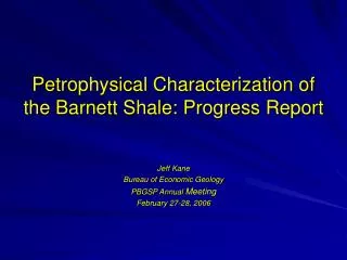
Barnett Shale Fracture Overview Julia F. W. Gale & Robert M. Reed Permian Basin Geological Synthesis Project Fracture Research and Application Consortium Julia F. W. Gale, PBGSP Annual Meeting
Barnett Shale Fracture Overview • Natural opening-mode fractures • Core observations • Distinguishing natural from induced fractures • Orientation, intensity, openness, height, aperture, connectivity • Fracture clustering • Geomechanical modeling and subcritical crack index measurements • Fracture porosity and storage capacity • Microfractures and fracture attribute scaling • Faults • Hydraulic fracture treatments • Microseismic observation of propagating fractures • Interaction with natural fractures • In situ stress • Conclusions
Extension (Mode I) Shear (Mode II) Shear (Mode III) Fracture Classification Twiss and Moores, 1997 Julia F. W. Gale, PBGSP Annual Meeting
Barnett Shale CoreFracture Description Texas United Blakely #1 Mitchell Energy Thomas P. Sims #2 Julia F. W. Gale, PBGSP Annual Meeting
Natural fracture at 6485’ Natural fracture approx 1ft high (length indeterminate, aperture >0.05 mm ) Inset: Cement growth on fracture surface Core piece missing – upper termination indeterminate Natural fracture Fracture surface with mineral growth (likely calcite) Lower termination indeterminate
Core breakup along shaley partings – stress release effect Core handling fractures at slabbed core edges (no mineral growth on surface) Fragments of thin walled brachiopods – parallel to bedding Other features distinct from natural fractures Natural fracture
En Echelon Fractures Fracture tips are mostly straight. En echelon fractures do not indicate shear in this case. They arise when stress intensity at a flaw rises above the level required for failure (probably subcritical growth) as other fractures propagate with elevated stress intensity at their tip. Note both right and left stepping examples.
En Echelon Fractures A few fracture tips curve towards each other. Might indicate moderate local stress anisotropy. More common in horizontal plane if SHmax and Shmin are close in magnitude.
Fractures in carbonate concretions Local to concretions only Multiple phases seal fractures 5 cm Julia F. W. Gale, PBGSP Annual Meeting
Natural Fracture Observations in Cores • Many narrow sealed opening-mode fractures • >24 in 103 ft (Blakely #1) • 20 in 14 ft (T.P. Sims #2) • Several groups of en-echelon fractures • All fractures are sealed • Widest 1.15 mm; narrowest < 0.05 mm; Tallest 68 cm • Concretions commonly fractured • Fractures local • Pale, dolomite-rich layers • Fracture intensity not greater than other lithologies (exception is Forestburg) • Number of sets may be higher • Vertical fracture terminations: gradual taper or abrupt at bedding planes with greater mud content Julia F. W. Gale, PBGSP Annual Meeting
Rose diagrams of natural fracture orientations T.P. Sims #2R. E. Hill 1992 GRI topical report Core fractures FMS fractures Julia F. W. Gale, PBGSP Annual Meeting
Sealed fractures Large open fractures Austin Chalk outcrop Comparison of fractures in Barnett Shale & Austin Chalk (fine-grained mudrock with carbonate layers & chalk with marl layers) Barnett Shale Narrow sealed fractures Austin Chalk
Subcritical index & network geometryGeomechanical modeling by Jon Olson (FRAC) • low n, spacing < bed thickness, early subcritical growth • high n, widely spaced clusters, late critical growth n=5 n=20 n=80
Subcritical crack index measurementsT.P. Sims #2 core samples • Fractures probably clustered • High subcritical crack index • En echelon arrays Tests by Jon Holder (FRAC)
(281) SEM Imaging of Fractures at 7,749 ft T.P. Sims #2 core Imaged with Secondary Electrons, Backscattered Electrons, and Cathodoluminescence, with EDS mapping • Two samples from 7,749 ft • shale • dolomitic layer below shale • Both samples have multiple fracture sets • Core oriented based on FMI log Backscattered electron image of 281°-trending fracture
Pyrite Calcite Dolomite Barite Albite Quartz Six Phases of Mineral Fill in Fracture Trending 281º Backscattered electron image (BSE) shows differences in atomic number, brighter indicates higher number Albite and quartz are not distinguishable in BSE False-color EDS element map Red = Si; Green = S; Blue = Ca This combination of elements best shows the 6 different phases. After R. M. Reed, 2004
(184) calcite + dolomite calcite pyrite calcite + dolomite (190) (262) horizontal thin section Cold-cathode CL image mosaic (280) Fractures in Dolomitic Layer ~N ~ same orientation as 6-phase fracture in shale
Crack-Seal Texture NS-trending fracture in dolomitic layer (UV-blue CL)
Fracture Orientation Rose DiagramSample from 7,749 ft, T. P. Sims #2 Core Oldest Calcite+ dolomite fill Crack-seal Youngest 6 phases of fill Calcite fill Youngest Calcite+dolomite +pyrite Open induced fractures or reactivation along natural fractures N=11 N=13 Circle = 27% Circle = 23% Fracture Trends, Dolomitic Sample Fracture Trends, Mudstone Sample
Fracture porosity, connectivity and storage capacity • Narrow natural fractures are sealed • Fracture system porosity low • If larger fractures open, permeability could be high • At least two fracture sets • Improves connectivity • Storage capacity low Julia F. W. Gale, PBGSP Annual Meeting
Faults in core Dip-slip faults in core with breccia and slickensides One fault trending 109°/55° SSW identified in the T.P. Sims #2 (Hill, 1992) Julia F. W. Gale, PBGSP Annual Meeting
Fault at 6,623 ft Slickenlines indicating dip slip Fault zone with breccia Calcite fill along fault Julia F. W. Gale, PBGSP Annual Meeting
Fault at 6,648 ft Fault plane slickenfibres Slab face (above) and fault plane (left) of 45° shallow, dip slip fault
Hydraulic Fracture Treatments • Provide permeability linked to the wellbore • Hydraulic fractures will initially propagate parallel to SHmax • Waterfracs pumped at high rates (rather than gel) • Monitored by microseismic • Vertical wells (seismic receivers in offset well) • Horizontal wells (need to monitor full extent of well and fractures) • Fracture height control – underlying Ellenburger Julia F. W. Gale, PBGSP Annual Meeting
3 2 2 1 3 3 Hydraulic fractures Hydraulic Fracture Treatments Monitoring fracture growth using microseismic detectors (Warpinski et al. 2005) • Waterfracs propagate parallel to SHmax (NE) • Reopen natural sealed NW fracs to link the system giving a 3D network • Fractures pop open because the fill does not template onto grains in the wall rock • Connect to and reopen NE trending natural fractures En echelon natural fractures
1 Hydraulic fractures Hydraulic Fracture Treatments • In some tight naturally fractured reservoirs connecting with the cross-trending fractures is seen as a problem • Premature screen out • Natural fracture damage • In Barnett Shale these problems are avoided by • Water rather than gel • Low proppant loadings En echelon natural fractures
In situ stress Present day in situ stress controls hydraulic fracture orientation Fort Worth Basin - in Mid-Plate Compression province West Texas,Culberson Co. and Reeves Co. - along boundary between Cordilleran Extension and Southern Great Plains (SGP) provinces - need to carefully establish SHmax Map modified from Zoback and Zoback (1989) and Laubach et al. 2004 FWB C/R Julia F. W. Gale, PBGSP Annual Meeting
Conclusions Fort Worth Basin • Many small sealed natural fractures trending NW • Possible larger open fractures • Less common sets NS and NE • Intrinsic storage capacity low • Reactivate during hydraulic fracturing West Texas • Stress province different • Uncertain in-situ stress – need to measure (FMI breakouts at least) • Unknown natural fracture orientation – evaluation required Julia F. W. Gale, PBGSP Annual Meeting