Download
1 / 47
470 likes | 829 Vues
Working at Height Design of Suspended Access. Raymond Gold – Managing Director RDG Engineering Ltd. The design of an access/protection system has the overarching commitment to provide protection for both the operatives above and employees, public and infrastructure alike below. .

E N D
Working at HeightDesign of Suspended Access Raymond Gold – Managing Director RDG Engineering Ltd
The design of an access/protection system has the overarching commitment to provide protection for both the operatives above and employees, public and infrastructure alike below.
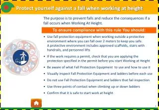
What is the design for? The construction of a platform or barrier that provides protection and segregation for a workforce carrying out the construction work above an active railway and public area alike.
What does the barrier comprise of? • A single level barrier A single level provides both the combined working and protection level.
What does the barrier comprise of? • Multilevel barrier Two or more levels are provided; usually the lowest one provides the ultimate protection, levels above provide access and load carrying capabilities.
Temporary Works Responsibilities Design Approval CRE Checker PM DPE Designer
Design Specification and Brief Network Rail Standards No specific standards for suspended access protection barriers, scaffolds or temporary access/protection structures
Design Specification and Brief Network Rail Standards BSI Standards - Scaffold / Access • BS 12811 Parts 1 & 2 Temporary works equipment. • BS 5974 Code of Practice for the planning, design, setting up and use of temporary suspended access equipment.
Design Specification and Brief Network Rail Standards BSI Standards - Scaffold / Access Industry Standards • NASC TG20:08Guide to Good Practice for • Scaffolding with Tubes and Fittings – • Volumes 1 & 2
Design Specification and Brief Network Rail Standards BSI Standards - Scaffold / Access Industry Standards BSI Standards – Structural Standards • Structural steelwork, Aluminium and Timber Standards
Design Specification and Brief Network Rail Standards BSI Standards - Scaffold / Access Industry Standards BSI Standards – Structural Standards ‘End user’ Specification • Work scope, performance specification and activity schedules
Design Specification and Brief Network Rail Standards • BSI Standards - Scaffold / Access Industry Standards BSI Standards – Structural Standards ‘End user’ Specification
Typical Customer Criteria Protection barrier against activities being undertaken • Safety in and ease of construction Provides weather/noise/fumes protection No impact on activities beneath barrier
Key Elements • Where ever possible structural redundancy should be incorporated in any design. • Protection against incremental collapse should be achieved by providing compartmentalised structures. • Normal design factors of safety employed for the above items.
Key Elements In many instances it is not possible to build-in an elements of redundancy as part of the standard solution. For these items either increased factors of safety are used or additional ‘fail-safe’ measures are incorporated.
Design Loads Erection loads Part completion Storage of construction materials Loads encountered during relocation
Design Loads Dead loads Self weight of component parts of primary structure Secondary access Additional protection Canopies Access routes
Design Loads Imposed loads - Platform working loads Blanket UDL Localised load bays and materials storage Materials transit routes Access routes
Design Loads Imposed loads - Platform imposed loads Snow Wind Services Dynamic Materials impact
Dynamic Loads Vibration Horizontal Vertical
Dynamic Loads Vibration: In general, plant vibration is unlikely to cause any significant increase in loading. However, the loosening effects on bolts, wedges and other friction connections should be considered, particularly when external vibrators are used.
Dynamic Loads Horizontal: Forces from moving plant, or from materials being deposited on or off the protection layer or being carried across the deck by plant or on moving equipment. Allow for horizontal forces in any of the possible directions of movement equivalent to 10% of the static load of the moving items where the rate of travel < 2 m/s. For speeds > 2 m/s the horizontal force should equate to 33% of the moving load.
Dynamic Loads Vertical: To allow for dynamic loading from loads moving vertically. The static loading of the moving item should be increased by 25% when using mechanically operated lifting gear, and by 10% when using manually operated lifting gear
Dynamic Loads Movement: To allow for dynamic effects resulting from distortion and flexing when relocating a suspended access/protection
Impact Loads ALL falling materials shall be contained A very tall order - Is this possible? - It MUST be possible!
Impact Loads What are the limits of acceptability for the structural performance of a decking material. • No structural damage to the barrier. • Penetration of the barrier but object contained, barrier to be repaired. • Object penetrates barrier, slowed by impact but continues falling. What constitutes failure?
Impact Loads Temporary Work Materials of construction Piece sizes and weight Tools and equipment Movement of materials Personnel falls What are the causes?
Impact Loads Demolition Work Removal of steelwork Cladding & rails Suspended services Air handling units What are the causes?
Impact Loads Permanent Work Removal of rivets & bolts New steel sections & plate Suspended services Permanent access systems What are the causes?
Impact Loads Typical 5 kg Weight Items crow bar; lump hammer; steel bracket; piece of glazing; scaffold tube; hand held tools shape, mass, distance
Impact Loads A metal object weighing 5 kg falling through a vertical distance of 5.0m and coming to an almost instantaneous rest has a potential force on impact of 250 kN (25 tonne)
Impact Loads Impact Load Values (kN) Impact force of a 5kg mass falling from 5 m Deflection on Impact (m)
Impact Loads Incidents due to: • Personnel falling/tripping whilst working • Losing grip on an item • Poor work practices • Failure of a component part • External force applied
Impact Loads Hand held chiselling machine e.g. Rivet chisel falls onto the protection/crash deck. The machine falls chisel point down and penetrates the deck but the body of the machine stops it falling through the deck. The chisel stops abruptly causing the chisel bit to be shaken free which then falls to the public area below Possible Scenario
Impact Loads • Is it possible to accurately determine impact loads and their effect? • On site testing of possible scenarios. Theoretical Design/Practical Tests
Construction Risks during construction of a protection platform can be mitigated by assembling as much of the platform at ‘ground’ level and elevate into position, or construct in elevated designated areas.
Construction The means of mitigating the risks associated when using a protection barrier are many and varied and range between: • selection of materials • reduction in vertical distance between the protection systems and the work zone • risk assessment and modifications to work practices commercial considerations that might be brought to bear.
Construction – Deck Materials • Profiled metal decking • Plain metal plate • Composite materials • Plywood • Scaffold boards • Netting • Rubber
Construction – Localised Materials • Polystyrene blocks • Air bags • ‘Bean’ bags • Netting • Metal plate • Fibreglass panels • Collapsible frames
Construction – Detailing • Connection details • Sealing of all gaps • Edge protection • Handrails • Encapsulation • Sealing around protuberances • Stepped access
Inspection • Standard 7 day inspection • Gaps, changes in use etc. • Bespoke inspections • Changes in edge protection • Sealing around protuberances
If All Else Fails Carry out work during possession and isolation periods?