Download
1 / 85
860 likes | 1.31k Vues
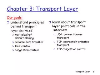
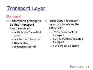
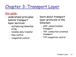
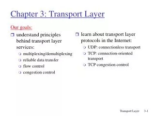
The Transport Layer The Transport Service & Elements of Transport Protocols. Chapter 6. Transport Service. Services provided to the Upper Layers Transport Service Primitives Berkeley Sockets Example of Socket Programming: Internet File Server. Services Provided to the Upper Layers.

E N D
The Transport LayerThe Transport Service &Elements of Transport Protocols Chapter 6
Transport Service • Services provided to the Upper Layers • Transport Service Primitives • Berkeley Sockets • Example of Socket Programming:Internet File Server
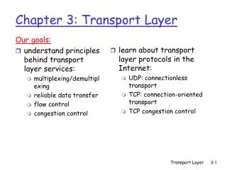
Services Provided to the Upper Layers Fig.: The network, transport, and application layers Transport layer responsibilities: • Establishment, data transfer and release • Make it more reliable than the underlying layer
Transport Service Primitives (1) The primitives for a simple transport service
Transport Service Primitives (2) Nesting of segments, packets, and frames.
Berkeley Sockets (1) A state diagram for a simple connection management scheme. Transitions labeled in italics are caused by packet arrivals. The solid lines show the client’s state sequence. The dashed lines show the server’s state sequence.
Berkeley Sockets (2) The socket primitives for TCP
Elements of Transport Protocols (1) • Addressing • Connection establishment • Connection release • Error control and flow control • Multiplexing • Crash recovery
Similarity between data link and transport layer • Connection establishment • Connection release • Error control and flow control
Elements of Transport Protocols (2) • Environment of the data link layer. • Environment of the transport layer.
Addressing (1) TSAPs, NSAPs, and transport connections
Addressing (2) How a user process in host 1 establishes a connection with a mail server in host 2 via a process server.
Connection Establishment (1) Techniques to enable receiver to distinguish between retransmitted packets and packets delivered late: • Throwaway transport addresses. • Assign each connection a different identifier:<Peer transport entity, connection entity> Limitation: Nodes have to maintain history information indefinitely.
Connection Establishment (2) Techniques for restricting packet lifetime: • Restricted network design. • Putting a hop counter in each packet. • Timestamping each packet.
Connection Establishment (3) 3 protocol scenarios for establishing a connection using a 3-way handshake. CR denotes CONNECTION REQUEST. (1) Normal operation.
Connection Establishment (4) 3 protocol scenarios for establishing a connection using a 3-way handshake. CR denotes CONNECTION REQUEST. (2) Old duplicate CONNECTION REQUEST appearing out of nowhere.
Connection Establishment (5) 3 protocol scenarios for establishing a connection using a 3-way handshake. CR denotes CONNECTION REQUEST. (3) Duplicate CONNECTION REQUEST and duplicate ACK.
Connection Release (1) Abrupt disconnection with loss of data – one way release or two way release
Connection Release (2) The two-army problem Synchronization which will go on infinitely
Connection Release (3) Four protocol scenarios for releasing a connection. (1) Normal case of three-way handshake
Connection Release (4) Four protocol scenarios for releasing a connection. (2) Final ACK lost.
Connection Release (5) Four protocol scenarios for releasing a connection. (3) Response lost
Connection Release (6) Four protocol scenarios for releasing a connection. (4) Response lost and subsequent DRs lost.
Error Control and Flow Control (1) (a) Chained fixed-size buffers. (b) Chained variable-sized buffers. (c) One large circular buffer per connection.
Error Control and Flow Control (2) • For low-bandwidth bursty traffic, it is better not to allot buffer on connection establishment. • Dynamic allotment of buffer a better strategy. • Decouple sliding window protocol.
Error Control and Flow Control (3) Dynamic buffer allocation. The arrows show the direction of transmission. An ellipsis (...) indicates a lost segment
Error Control and Flow Control (4) • Assuming buffer size is infinite, carrying capacity becomes a bottleneck. • If adjacent routers can exchange at most x packets/sec, and there are k disjoint paths between a pair of hosts, max. rate of segment-exchange between hosts = kx segments/sec
Multiplexing (a) Multiplexing. (b) Inverse multiplexing.
Crash Recovery Different combinations of client and server strategies
Congestion Control • Desirable bandwidth allocation • Regulating the sending rate
Desirable Bandwidth Allocation (1) (a) Goodput and (b) Delay as a function of offered load
Desirable Bandwidth Allocation (2) • Best network performance when bandwidth is allocated up to when delay shoots up. • Power: Power = Load / Delay • Power rises initially with load. • Reaches maximum and falls when delay grows rapidly. • Load with highest power – efficient load.
Desirable Bandwidth Allocation (3) • Notion of max-min fairness. • B/w given to one flow can’t be increased without decreasing b/w for another flow, by an equal amt. Max-min bandwidth allocation for four flows
Desirable Bandwidth Allocation (4) • Convergence: Good congestion control algorithm should rapidly converge to ideal point. • It should track ideal operating point over time. Changing bandwidth allocation over time
Regulating the Sending Rate (1) • A fast network feeding a low-capacity receiver. • A slow network feeding a high-capacity receiver.
Regulating the Sending Rate (2) Signals of some congestion control protocols
Regulating the Sending Rate (3) Additive and multiplicative bandwidth adjustments
Regulating the Sending Rate (4) Additive Increase Multiplicative Decrease (AIMD) control law.
Congestion Control in Wireless Congestion control over a path with a wireless link
The Internet Transport Protocols:UDP (User Datagram Protocol) • Introduction to UDP • Remote Procedure Call • Real-Time Transport
Introduction to UDP (1) The UDP header. • Source port field from incoming segment is copied to destination port field of outgoing segment. • UDP length field includes 8-byte header, and data. • Optional checksum field for extra reliability: checksums header, data and IP pseudo-header.
Introduction to UDP (2) The IPv4 pseudo-header included in the UDP checksum. • UDP does not do flow-control, congestion control, retransmission. • Does de-multiplexing of multiple processes using ports. • Does optional end-to-end error detection. • UDP useful in client-server situations; client sends short request to server & expects short reply. If time-out, retransmit. • Use-case: Sending host name to a DNS server.
Remote Procedure Call (RPC) Steps in making a remote procedure call. The stubs are shaded. • Packing the parameters is called marshalling. • Example: get_IP_address (host name)
Call-by-reference call-by-copy-restore Doesn’t work if it has complicated data structure • If the value is not know – like inner product of vectors • Type – pintf (mix of parameters) • Global variables • Run by UDP..
Operations need to be idempotent (i.e. safe to repeat) like DNS • If reply is larger than the largest possible UDP packets - • multiple requests overlap - proper synchronization is required
Real-Time Transport Protocol (1) (a) The position of RTP in the protocol stack. (b) Packet nesting.
Real-Time Transport Protocol (2) • It is difficult to say which layer RTP is in – generic and application independent. • Best Description: transport protocol implemented in the application layer. • Basic Function of RTP: multiplex several real-time data streams onto a single stream of UDP packets. • Each packet is given a number one higher than its predecessor. • Allows the destination to determine whether any packets are missing; then interpolate. • Another usage: timestamping – relative values are obtained. • Allows multiple streams (audio/video) to combine together.
The multimedia application consists of multiple audio, video, text, and possibly other streams. • These are fed into the RTP library, which is in user space along with the application. • This library multiplexes the streams and encodes them in RTP packets, which it stuffs into a socket.
RTP defines several profiles (e.g., a single audio stream), and for each profile, multiple encoding formats may be allowed. • For example, a single audio stream may be encoded as 8-bit PCM samples at 8 kHz using delta encoding, predictive encoding, GSM encoding, MP3 encoding, and so on. • Timestamping reduce the effects of variation in network delay, but it also allows multiple streams to be synchronized with each other.
Real-Time Transport Protocol (3) The RTP header