Download
1 / 14
140 likes | 160 Vues
Comprehensive testing setup to verify components of ATLAS L1 Calorimeter Trigger System for efficient particle identification and event selection.

E N D
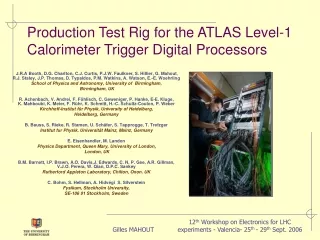
Production Test Rig for the ATLAS Level-1 Calorimeter Trigger Digital Processors J.R.A Booth, D.G. Charlton, C.J. Curtis, P.J.W. Faulkner, S. Hillier, G. Mahout, R.J. Staley, J.P. Thomas, D. Typaldos, P.M. Watkins, A. Watson, E.-E. Woehrling School of Physics and Astronomy, University of Birmingham, Birmingham, UK R. Achenbach, V. Andrei, F. Föhlisch, C. Geweniger, P. Hanke, E-E. Kluge, K. Mahboubi, K. Meier, F. Rühr, K. Schmitt, H.-C. Schultz-Coulon, P. Weber Kirchhoff-Institut für Physik, University of Heidelberg, Heidelberg, Germany B. Bauss, S. Rieke, R. Stamen, U. Schäfer, S. Tapprogge, T. Trefzger Institut fur Physik, Universität Mainz, Mainz, Germany E. Eisenhandler, M. Landon Physics Department, Queen Mary, University of London, London, UK B.M. Barnett, I.P. Brawn, A.O. Davis,J. Edwards, C. N. P. Gee, A.R. Gillman, V.J.O. Perera, W. Qian, D.P.C. Sankey Rutherford Appleton Laboratory, Chilton, Oxon. UK C. Bohm, S. Hellman, A. Hidvégi S. Silverstein Fysikum, Stockholm University, SE-106 91 Stockholm, Sweden Gilles MAHOUT
ATLAS Level-1 Calorimeter Trigger System Calorimeters Muon Tracking Calo Muon Muon Trigger CalorimeterTrigger 75 kHz L1 jet e/g tau Et SE m Fifo ReadoutDriver ROD ROD ROD 1000 Hz R O B R O B R O B Central Trigger Processor ReadoutBuffer L2 Event Builder Region ofInterest (RoIs) 200 Hz Front EndBuffer Storage Gilles MAHOUT
Identifying Clusters: e/g, tau and jets • The trigger works on a reduced granularity with trigger towers covering 0.1 x 0.1 in x • The e.m. and tau are based on windows of 4 x 4 trigger towers, in both e.m. and hadronic calorimeters • The jet trigger is based on windows of 4 x 4 “jet elements”, each 0.2 x 0.2 in x , with e.m and hadronic calorimeters summed • This windows slide in eta and phi to fully cover the calorimeter • RoIs are defined by their (h,f) coordinates – a window is a local candidate trigger object if it is a local maximum • RoIs are tested against sets of threshold values, each made up of cluster and, (for e.m. and tau) isolation energies. Module 3 Module 0 Module 2 Module 1 • Because the algorithms involve overlapping data, Trigger Tower data are shared: • between algorithm chips onboard • between modules, across a custom-built backplane Gilles MAHOUT
System Data flow ~7200 Calorimeter Trigger Towers Jet/EnergyProcessor 141 GBytes/s Pre-Processor 589 GBytes/s 0.7 GBytes/s CentralTriggerProcessor ClusterProcessor 75 kHz 448 GBytes/s L1A DataCheck RoI Readout Level 2 Gilles MAHOUT
To DAQ Slow Control RoI RODs TTC 0.1 x 0.1 Jet / ET (JEP) Pre- Processor (PPr) 0.2 x 0.2 CANbus ATLAS Level-1 Calorimeter Trigger System Input/output data DAQ RODs 2 ROD crates To CTP To L2 2 JEP crates Feature types/ positions e/, /had Clusters (CP) Analogue tower sums0.1 x 0.1 (~7200) (>300 Gbyte/s) To CTP 8 PPr crates 4 CP crates Fibre F/O DCS CTP Gilles MAHOUT
Level-1 Calorimeter Trigger System: Production Test Rig • All digital boards have passed their Production Readiness Review pending a full crate test made on pre-production modules: Cluster Processor Modules and Jet/Energy Modules. • Need to gear up to the equivalent of ¼ of full trigger in one crate • Additional production boards were manufactured • Need to emulate calorimeter LVDS: special boards have been built to source data • Ordered LVDS cables with final ATLAS length • 1888 4-link cables needed for final system, around 300 per crate • Production custom-built backplane available for the test • Additional tests • Generate 18 active links to fully populate the ROD input • Test of the DCS with a full crate of boards: • Monitoring on-board currents, voltages and temperatures using PVSS • Simulation of the hardware easily expandable to accommodate several crates and modules Gilles MAHOUT
Calorimeter signals: LVDS Source Modules • Custom built LVDS Source Modules (LSM) have been used as source of 400 Mbit/s serial LVDS • 1 LSM per board • Custom backplane receives the emulated calorimeter LVDS from the rear • Final number • 308 cables • 14 LSMs • 28 TTCrx chips on mezzanine board Gilles MAHOUT
Cluster Processor Module: Full Crate Test • Contents of the crate • 14 CPMs • 1 CPU mounted on a special adaptor card to fit the custom backplane • 1 board designed to broadcast the TTC clock to each individual module via the backplane; also provide interface to external CANbus • 2 Common Merger Modules Gilles MAHOUT
Cluster Processor Module: Crate Test results • Patterns used • Ramp to test LVDS input • Test vector with programmable occupancy rate • Long term measurement • No parity error observed in 5 hours on real time data directly seen from the source, or through backplane • Timing window investigation • For the fastest links, data across backplane show parity error free window of 2 ns • Crate Power Consumption • ~ 200 A at 10% occupancy (<300 A, in PSU specification) • P ~ 1 kW • FPGA behaviour • Big FPGA temperature less than 45oC • Internal current within specification Chip # (.1 ns) Gilles MAHOUT
Jet/Energy Module: Crate Test Results • Contents of the crate as before, but with 7 JEMs instead of CPMs • Empty slot between board types to avoid data mismatched across backplane • Results: • No links lost on LVDS • No parity errors observed after 5 hours across the backplane • 10-bits Ramp Gilles MAHOUT
Common Merger Module • Two CMMs in crate • No parity errors in 5 hours on backplane data • All CMM inputs show wide parity error free windows with CPMs as inputs No boards 10 ns Parity Errors NoParity Errors (.1ns) Gilles MAHOUT
ROD can receive up to 18 modules via G-links 16 boards connected Results: No parity errors observed in 1 hour 5 CPMs feeding ROD had no data errors after 200k events ROD Test Gilles MAHOUT
Detector Control System on crate • CANbus using CANOpen protocol to read out all temperatures and currents of up to 14 modules • PVSS used to monitor currents, voltages and temperatures • Alarm implemented and successfully tested • Overnight runs possible during production phase Gilles MAHOUT
Conclusions • The full-crate tests have been successful: • Debug early problems in comfort of the laboratory rather than in the ATLAS pit • Check stability of the digital board designs • Check crate power consumption • Scale up DCS to several boards and crates • All boards are into production now • First production modules are now being used in ATLAS pit Gilles MAHOUT