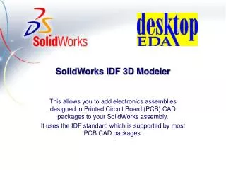
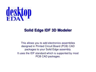
Solid Edge IDF 3D Modeler: Efficient Electronics Assembly Integration Tool
Solid Edge IDF 3D Modeler enables adding PCB assemblies to Solid Edge designs using IDF standards, supported by leading ECAD packages. Create assemblies from IDF files or generate IDF files from Solid Edge assemblies with ease. This tool simplifies the integration process by providing user-friendly features and support for various ECAD systems.

Solid Edge IDF 3D Modeler: Efficient Electronics Assembly Integration Tool
E N D
Presentation Transcript
Solid Edge IDF 3D Modeler This allows you to add electronics assemblies designed in Printed Circuit Board (PCB) CAD packages to your Solid Edge assembly. It uses the IDF standard which is supported by most PCB CAD packages.
Creates a Solid Edge assembly from IDF files Creates IDF files from a Solid Edge assembly How Does it Work?
ECAD Packages Supported • Mentor • Cadence • Pads • P-CAD • Protel • ORCAD • Veribest • Any that supports IDF
Creating An Assembly from IDFFiles • Use the Import IDF toolbar button • The IDF Import dialog box displays…
Import Tab IDF Board File IDF Library File Assembly Directory
Settings Tab Directory for Solid Edge parts Edit IDF part heights Color settings for auto created parts
Options Tab Select PCB hole types to Import Select IDF Features to Import
Select Parts Tab If any boxes checked, only selected parts are imported
Board Tab View the IDF Board file
Library Tab View the IDF Library file
Part for PCB is automatically created Parts from Library
Non Plated Holes Plated Holes
If no library parts are available, the program automatically creates parts
Top Parts Printed Circuit Board Part Bottom Parts
Creating IDF Files from An Assembly • Use the Export IDF toolbar button • The IDF Export dialog box displays…
Set name of IDF files Choose target ECAD system Choose IDF version Choose IDF units
Export searches for Parts by their name in the Edge Bar to get PCB geometry Export uses Part Edge Bar name to create IDF file entries To get part geometry, Export uses known feature names in Parts if present, otherwise uses the bounding cube
Starting a New PCB Design in Solid Edge • Use the New ECAD Assembly toolbar button • Creates a “template” assembly with all features appropriately named ready for Export • The user modifies this Assembly as required
Features with correct names ready to modify Top and bottom template parts – copy and rename to create more parts
Full IDF Support Top Place Outline Place Keepout Bottom Place Outline
Solid Edge IDF 3D Modeler Features • Supports IDF versions 2 and 3 • Supports top and bottom placed parts • Bi-directional • Supplied with electronics parts library • Automatically creates parts if no library parts available • Fully supports the IDF Specification – route outlines, keep-outs etc.