Download
1 / 78
780 likes | 902 Vues
Multiple-Valued Logic:. Introduction. By Marek Perkowski Some slides of M. Thornton used. Introduction: What is the sense in MV logic. THE MULTIPLE-VALUED LOGIC. What is it? WHY WE BELIEVE IT HAS A BRIGHT FUTURE. Research topics (not circuit-design oriented) New research areas

E N D
Multiple-Valued Logic: Introduction By Marek Perkowski Some slides of M. Thornton used
THE MULTIPLE-VALUED LOGIC. • What is it? • WHY WE BELIEVE IT HAS A BRIGHTFUTURE. • Research topics (not circuit-design oriented) • New research areas • The need of unification
Is this whole a nonsense? • When you ask an average engineer from industry, he will tell you “multi-valued logic is useless because nobody builds circuits with more than two values” • First, it is not true, there are such circuits built by top companies (Intel Flash Strata) • Second, MV logic is used in some top EDA tools as mathematical technique to minimize binary logic (Synopsys, Cadence, Lattice) • Thirdly, MV logic can be realized in software and as such is used in Machine Learning, Artificial Intelligence, Data Mining, and Robotics
MIN MAX Short Introduction: multiple-valued logic Signals can have values from some set, for instance {0,1,2}, or {0,1,2,3} {0,1} - binary logic (a special case) {0,1,2} -a ternary logic {0,1,2,3} - a quaternary logic, etc 1 Minimal value 1 2 21 23 Maximal value 2 3 23
Binary logic is doomed • It dominates hardware since 1946 • Many researchers and analysts believe that the binary logic is already doomed - because of Moore's Law • You cannot shrink sizes of transistors indefinitely • We will be not able to use binary logic alone in the generation of computer products that will start to appear around 2020.
Quantum phenomena • They will have to be considered in one way or another • It is not sure if standard binary logic will be still a reasonable choice in new generation computing • Biological models
Future “Edge” of MVL • Chip size and performance are increasingly related to number of wires, pins, etc., rather than to the devices themselves. • Connections will occupy higher and higher percentage of future binary chips, hampering future progress around year 2020. • In principle, MVL can provide a means ofincreasing data processing capability per unit chip area. • MVL can create automatically efficient programs from data
From two values to more values • The researchers in MV logic propose to abandon Boolean principles entirely • They proceed bravely to another kind oflogic, such as multi-valued, fuzzy, continuous, set or quantum. • It seems very probable, that this approach will be used in at least some future calculating products.
Multi-Valued Logic Synthesis(cont) • The MVL research investigates • Possible gates, • Regular gate connection structures (MVL PLA), • Representations - generalizations of cube calculus and binary decisiondiagrams (used in binary world to represent Boolean functions), • Application of design/minimization algorithms • General problem-solving approaches known from binary logic such as: • generalizations of satisfiability, graph algorithms or spectral methods, • application of simulated annealing, genetic algorithms and neural networks in the synthesis of multiple valued functions.
Binary versus MV Logic Synthesis Research • There is less research interest in MVL because such circuits are not yet widely used in industrial products • MV logic synthesis is not much used in industry. • Researchers in hundreds • Only big companies, military, government. IBM • The research is more theoretical and fundamental. • You can become a pioneer – it is like Quine and McCluskey algorithm in 1950 • Breakthroughs are still possible and there are many open research problems • Similarity to binary logic is helpful.
However………, • if some day MV gates were introduced to practical applications, the markets for them will be so large that it will stimulate exponential growth of research and development in MV logic. • and then, the accumulated 50 years of research in MV logic will prove to be very practical.
Applications • Image Processing • New transforms for encoding and compression • Encoding and State Assignment • Representation of discrete information • New types of decision diagrams • Generalized algebra • Automatic Theorem Proving
The Shortest History of Multi-Valued Logic
Jan Lukasiewicz (1878-1956) • Polish minister of Education 1919 • Developed first ternary predicate calculus in 1920 • Many fundamental works on multiple-valued logic • Followed by Emil Post, • American logician born in Bialystok, Poland
MV functions of single variable 2 2 2 • Post Literals: 1 1 1 0 1 2 0 1 2 0 1 2 • Generalized Post Literals: 2 2 2 1 1 1 0 1 2 0 1 2 0 1 2
= negation 2 1 0 2 1 0 = wire 0 1 2 MV functions of single variable (cont) • Universal Literals: 0 1 2 2 2 1 1 0 1 2 0 1 2
Multiple-Valued Logic a b c 0 1 2 00 2 2 2 01 - - 0,2 02 1,2 1,2 0,1 10 2 2 - 11 2 2 - 12 0 0 0 20 1 2 2 21 - 2 2 22 0 0 - • Let us start with an example that will help to understand, Suppose that we have the following table, and we need to build a circuit with MV-Gates, (MAX & MIN). As we can see, this is ternary logic.
a b c 0 1 2 00 2 2 2 01 - - 0,2 a0,1 b0,1 02 1 1 0,1 10 2 2 - b0,1 c1,2 11 2 2 - 12 0 0 0 a0,1 b0,1 + b0,1 c1,2 “Covering 2’s in the map” 20 1 2 2 21 - 2 2 22 0 0 -
ab c 0 1 2 00 - - - a0 01 - - - 02 1 1 1 10 - - - 11 - - - b0,1 12 0 0 0 20 1 - - 21 - - - 1.a0,1 +1.b0,1 “Covering 1’s in the map” 22 0 0 -
MVL Circuits MAX-gate MIN-gate
SOP = a0,1 b0,1 + b0,1 c1,2+ 1.a0,1 +1.b0,1 a 0,1 Min b 0,1 Min c 1,2 Max f Min 1 Min 1
Example of Application of logic with MV inputs and binary outputs to minimize area of custom PLA with decoders. 0 1 a b • Pair of binary variables corresponds to quaternary variable X • a’+b’=X012 • a’+b=X013 a + b’ = X023 0 1 0 1 2 3 a + b = X123 (a + b’) *(a’+b)= X023 * X013 Thus equivalence can be realized by single column in PLA with input decoders instead of two columns in standard PLA
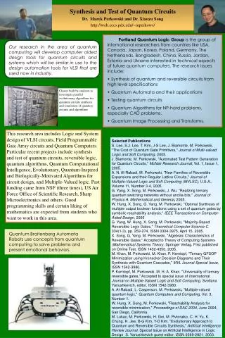
Multiple Valued Logic • Currently Studied for Logic Circuits with More Than 2 Logic States • Intel Flash Memory – Multiple Floating Gate Charge Levels – 2,3 bits per Transistor http://www.ee.pdx.edu/~mperkows/ISMVL/flash.html • Techniques for Manipulation Applied to Multi-output Functions • Characteristic Equation • Positional Cube Notation (PCN) Extensions
MVI Functions • Each Input can have Value in Set {0, 1, 2, ..., pi-1} • MVI Functions • X is p-valued variable • literal over X corresponds to subset of values of S {0, 1, ... , p-1} denoted by XS
MVL Literals • Each Variable can have Value in Set {0, 1, 2, ..., pi-1} • X is a p-valued variable • MVL Literal is Denoted asX{j}Wherejis the Logic Value • Empty Literal: X{} • Full Literal has Values S={0, 1, 2, …, p-1} X{0,1,…,p-1} Equivalent to Don’t Care
MVL Example • MVI Function with 2 Inputs X, Y • X is binary valued {0, 1} • Y is ternary valued {0, 1, 2} • n=2 pX=2 pY=3 • Function is TRUE if: • X=1 and Y= 0 or 1 • Y=2 • SOP form is: • F = X{1}Y{0,1} + X{0,1}Y{2} • Literal X{0,1} is Full, So it is Don’t Care • implicant is X{1} Y{0,1} • minterm is X{1}Y{0} • prime implicants are X{1} and Y{2} X F Y
Standard PLA PLA with decoders X012 x a b X013 x X023 x X123 Y012 x cd Y013 x Y023 Y123 x x x Z=T1+T2 decoders T1= (a’ b) (c d) T2 = (a’ + b’) (c’ + d)
PLA with decoders • Such PLAs can have much smaller area thans to more powerful functions realized in columns • The area of decoders on inputs is negligible for large PLAs • Multi-valued logic is used to minimize mv-input, binary-output functions with capital letter inputs X,Y,Z,etc.
Multi-output Binary Function x f0 y • Consider f1 z
Characteristic Equation Multi-output Binary Function W x F y z • Consider x f0 y f1 z
Characteristic Equation Sum of Minterms
Positional Cube Notation (PCN) for MVL Functions • Binary Variables, {0,1}, Represented by 2-bit Fields • MV Variables, {0,1,…,p-1}, Represented by p-bit Fields • BV Don’t Care is 11 • MV Don’t Care is 111…1 • MV Literal or Cube is Denoted by C()
PCN for MVL Example • Positional Cube Corresponding to X{1} is C(X{1}) • Since Y{0,1,2} is Don’t Care
PCN for MVI-BO Example • View This as a SOP of MVI Function: • F is the Characteristic Equation
List Oriented Manipulation • Size of Literal = Cardinality of Logic Value Set x{0,2} size = 2 • Size of Implicant (Cube, Product Term) = Integer Product of Sizes of Literals in Cube • Size of Binary Minterm = 1 Implicant of Unit Size EXAMPLE f (x1,x2,x3,x4,x5,x6)
Logic Operations • Consider Implicants as Sets • Apply (, , , etc) • Apply Bitwise Product, Sum, Complement to PCN Representation • Bitwise Operations on Positional Cubes May Have Different Meaning than Corresponding Set Operations EXAMPLE Complement of Implicant Complement of Positional Cube
MVL Logical Operations • AND Operation – MIN - Set Intersection • OR Operation – MAX - Set Union • NOT Operation – Set Complement EXAMPLE
Cube Merging • Basic Operation – OR of Two Cubes • MVL Operation – MAX is Union of Two Cubes EXAMPLE = 1 {0,1} 0 1= 0 {0,1} 0 1 Merge and into = {0,1} {0,1}0 1
Minimization Example (cont) Sum of Minterms (Fig. 10.7 PLA Implementation) Merging • Merge 1st and 2nd • Merge 3rd and 4th • Merge 5th and 6th • Merge 7th and 8th
Minimization Example (cont) Multi-Output Function Using of Multi-Output Prime Implicants (Fig. 10.8 PLA Implementation)
Why we need Multiple-Valued logic? • In new technologies the most delay and power occurs in the connections between gates. • When designing a function using Multiple-Valued Logic, we need less gates, which implies less number ofconnections, then less delay. • Same is true in case of software (program) realization of logic • Also, most the natural variables like color, is multi-valued, so it is better to use multi-valued logic to realize it instead of coding it into binary.