Download
1 / 31
310 likes | 522 Vues
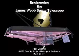
James Webb Space Telescope : Characterization of Flight Candidate of Raytheon NIR InSb Arrays. 5 Aug 2003 Craig McMurtry, William Forrest, Andrew Moore, Judith Pipher. Overview. Introduction Calibration of InSb SB-304 SCAs Dark current Noise QE Latent or Persistent Image Performance

E N D
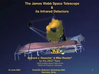
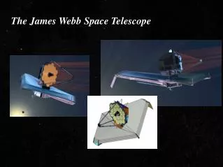
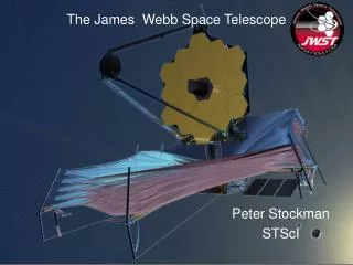
James Webb Space Telescope : Characterization of Flight Candidateof Raytheon NIR InSb Arrays 5 Aug 2003 Craig McMurtry, William Forrest, Andrew Moore, Judith Pipher
Overview • Introduction • Calibration of InSb SB-304 SCAs • Dark current • Noise • QE • Latent or Persistent Image Performance • Operability • Radiometric Stability
Introduction • Raytheon Detectors Proposed for JWST NIRCam and NIRSpec • InSb photo-diode detector technology • 0.5 – 5.3 mm photo-response • Based on SB-304 Read Out Integrated Circuit (ROIC) or multiplexer • 2048 x 2048 active pixels • 2 columns of 2048 reference pixels multiplexed to four outputs • Total readout format is 2056 x 2048 • University of Rochester provided detector array testing facilities for JWST level requirements
Calibration • Source Follower Gain • Gain through two SF FETs • SCA 006 SFGain=0.777 • SCA 008 SFGain=0.785 • Capacitance • Noise2 vs Signal method • SCA 006 • 66 fF • 3.22 e-/ADU • SCA 008 • 68 fF • 3.32 e-/ADU
Calibration • Linearity • Plotted Signal Rate vs Signal (C0/C) • Small flux over long integration times • Well Depth (Capacity) • @ 300 mV applied detector bias • SCA 006 well depth = 1.4 x 10⁵ e- • SCA 008 well depth = 1.3 x 10⁵ e- • Larger well depths possible with little or no increase in dark current
Dark Current Test Methods • Dark dewars are difficult to make and keep dark • Using an opaque mask placed in contact with InSb surface, UR dewar light leak < 0.006 e-/s • 3 Methods of measurement • Usually yield same values, although some discrepancies possible • Dark Charge versus integration time • With reference pixel correction, accurate for moderate dark currents • Lengthy measurement
Dark Current Test Methods • Noise2 versus integration time • With reference pixel correction, accurate for small dark currents • Also, lengthy measurement
Dark Current Test Methods • SUTR Dark Charge vs. time • With reference pixel correction, accurate for small dark currents • Relatively short measurement (single 2200 sec integration) • Addition of possible charge per read (e-/read) due to higher read rate • Confuses measured dark current • No detectable added noise from charge per read due to higher read rate!
Dark Current Results • SCA 006 • Idark = 0.012 e-/s @ T=30.0K • Idark = 0.024 e-/s @ T=32.3K • Charge per read of 0.09 e-/read • Again, no detectable noise due to this charge • No measurable amp glow or digital circuit glow
Dark Current Results • SCA 008 • Idark = 0.025 e-/s @ T=30.0K • Charge per read of 0.07 e-/read • No digital circuit glow • Slight glow (0.05 e-/s including dark current) from output amplifier • Covers small region (see operability section) • Known multiplexer defects (shorts) • Amp glow not seen on other multiplexers
System Noise • System Noise • Shorting resistor placed between signal (video) and signal reference lines (analog ground) • T=295K • Connected and functioning detector in dewar to allow typical voltage/current paths which may cause cross talk (worst case)
Read Noise • Read noise versus Fowler Sampling • Measured at T=30.0K • All integration times are 100 s • SCA 006 read noise results • Follows 1/sqrt(N) where N is the number of Fowler sample pairs
Read Noise • SCA 008 read noise results • Follows 1/sqrt(N)
Noise Measurement Methods • Methods of measurement for total noise in 1000 seconds. • Box average (often called “spatial” noise method) uses the {standard deviation of mean}/sqrt(2) of difference of two 1000 sec Fowler-8 images • Full frame average (“spatial”) noise computed using difference of two 1000 sec Fowler-8 images, and plotting histogram of pixel values • The width of the distribution corresponds to the average noise; mean is DC offset • Gaussian fit reject Cosmic Ray • SCA 006 at right
Noise Measurement Methods • Methods of measurement (cont) • Temporal noise measurement is computed by taking the standard deviation of the mean per pixel for a large number of 1000 sec Fowler-8 images (time series) • Distribution is typically a Gaussian whose width depends on the number of images taken. • Cosmic Ray hits removed from single images (4 s clipping).
Total Noise Results • Total Noise Requirement: < 9 e- in 1000 sec using Fowler-8 sampling • SCA 006 • 6.2 e- (Temporal method), 6.7 e- (Full frame spatial method) @ T=30.0K • 6.4 e- (Full frame spatial method) @ T = 32.3K • For 1000 sec Fowler-1, total noise is 12.0 e- (temporal method) @T=30.0K • SCA 008 • 7.9 e- (temporal method) @ T=30.0K
Quantum Efficiency • Photon sources and calibration equipment • For l > 3.0 mm, photon source is room temperature black body surface monitored with a calibrated temperature sensor • Subtract “extra signal” from image taken of liquid nitrogen cup • For 1.0 mm < l < 3.0 mm, photon source is NIST calibrated black body (Omega BB-4A, 100 – 1000 C, e =0.99) • For l<1.0 mm, photon source is stabilized visible light source feeding an integrating sphere with a NIST calibrated Si diode detector • cos4q corrected • Responsive Quantum Efficiency • RQE = signal/(expected #photons) • Signal is averaged signal measurement, corrected for non-linearity • Expected # photons from NIST calibrated detector or spectral black body calculations • Detective Quantum Efficiency • DQE = (Signal/Noise)2/(expected #photons) • Noise obtained via standard deviation of difference of two measurements
Quantum Efficiency Results DQE closely matches expected value from AR coating transmission as provided by Raytheon. From this, we infer that the optical fill factor is > 98%.
Test # Srce Flux (e-/s) Source Exposure (s) Source Fluence (e-) Delay (s)* Latent Integr’n Time (s) Max. Desired Latent Fluence (e-: %) Meas’d (%) Latent Fluence SCA006 ; SCA008 Latent Image Results 1 300 100 30,000 30 100 9 ; 0.03 0.3 ; 0.12 2 300 100 30,000 1000 100 0.9 ; 0.003 0.017 ; ≤0.01 3 30 1000 30,000 30 1000 4.5 : 0.015 ; 4 300 500 150,000 30 100 90 ; 0.06 0.48 ; 0.22 5 300 500 150,000 1000 100 9 ; 0.006 0.03 ; ≤0.01 6 3 10,000 30,000 200 8000 Noise level 7 15 10,000 150,000 200 8000 Noise level
Operability • Operability is affected by two types of defects: • Missing contact between InSb diode implant and multiplexer unit cell • First InSb bump-bonding to mux had moderate outages. • Significant strides made in very short time (see next slides). • PEDs (Photo-emissive defects) • Defect centers that glow (both IR and visible photons). • Techniques in place which either eliminate or dramatically reduce glow region such that ~20-40 pixel diameter region fail operability. • Future multiplexers will have additional circuitry to fully eliminate all PEDs. • Foundry improvement to reduce/eliminate defects.
Operability • SCA 006 • Basic Fail = 13.5% • Large fraction failing are unconnected pixels
Operability • SCA 008 • Basic Fail = 1.94% • Slight amp glow in lower left
Radiometric Stability • Method of measurement • Using similar technique as RQE measurement at l= 3.50 mm, a room temperature black body source was the source of “stable” flux. • A calibrated temperature sensor was used to monitor/calibrate variations in the temperature of the black body (radiation source). • A series of integrations were then taken over a 9 hour period. • Most of the errors or inaccuracies in this measurement are a result of source calibration error or instabilities in our system electronics and not due to the SCA itself. • Result • SCA 006 exhibited instabilities < 0.07% over 1000 s and < 0.19% over the total 32000 s. • Further improvement by factor of 10 - 100 may be gained by using our NIST calibrated black body source.
MTF and Electrical Cross-Talk • MTF • Measured using knife edge and circular apertures placed in contact with InSb surface • Edge spread functions shown for two wavelengths • Edge spread modeled by diffusion and rectangular pixel function which is the ratio of {pixel pitch/ distance between photon absorption and the depletion region}
MTF and Electrical Cross-Talk • MTF results (cont.) • From the best fit model parameter, z (frequency in cycles/thickness) can be determined, which in turn leads to MTF: MTF = 0.64 (2 e –2pz)/(1 + e-4pz) • If Nyquist frequency is taken as ½ z, then MTF = 0.45 • Similar measurement on SB-226 InSb SCA produced MTF=0.52 • If Nyquist frequency is taken as ¼ z, as in Rauscher’s MTF document, then MTF = 0.58 • Exceeds (existing) requirement of 0.53 in JWST NASA 641 document
MTF and Electrical Cross-Talk • Cosmic ray hit pixel upsets used to quantify electrical cross-talk • Histogram of 30K dark data difference showing peaks at 0.1% for next nearest neighbors and 0.5-1.2% for nearest neighbors • Cross talk is < 2%
0 0.025 0.012 0.025 0.012 -0.025 0.037 -0.037 0.012 0.099 MTF and Electrical Cross-Talk 0 -0.025 0.074 0.546 0.099 0 0.037 -0.012 0.025 -0.062 0.012 -0.050 1.142 100 0.782 0.137 -0.248 2.062 -0.211 0.012 0.062 0.012 0.161 0.733 0.012 0.062 -0.074 0 -0.050 0 0.025 -0.062 -0.037 0.012 0.012 0 0.074 0.025 0.012 0.001 • 4th pixel over electrical cross-talk • 4 interleaved outputs = next pixel on same output is 4 pixels away • Deterministic, can be removed or corrected in software • Below is a table of pixel values in percentage of a single cosmic ray event; notice 4th pixel over is 2%
Additional Tests • NASA Ames conducted proton radiation testing at UC Davis • Please see talk “Radiation environment performance of JWST prototype FPAs” 5167-25 on Wednesday • STScI IDT Lab conducted independent tests on both InSb detector arrays from Raytheon and HgCdTe detector arrays from Rockwell Scientific. • Please see talk “Independent testing of JWST detector prototypes” 5167-29 on Wednesday
Conclusions • Raytheon has produced a robust, mature technology. • Both the InSb detector arrays from Raytheon and the HgCdTe detector arrays from Rockwell Scientific have demonstrated excellent performance. • The University of Arizona has selected Rockwell Scientific to produce the NIRCam SCAs and FPAs. • Congratulations to UH and RSC!