CSE3213 Computer Network I
Explore the functionalities and advantages of LAN bridges, alongside an overview of channelization and Ethernet protocols. Learn the basics of LAN structures and IEEE standards in networking.

CSE3213 Computer Network I
E N D
Presentation Transcript
CSE3213 Computer Network I Channelization (6.4.1-6.4.2) LAN (6.6) Ethernet(6.7) Token-Ring (6.8.1) Wireless LAN(6.10) LAN Bridges(6.11.1) Course page: http://www.cse.yorku.ca/course/3213 Slides modified from Alberto Leon-Garcia and Indra Widjaja
Why Channelization? • Channelization • Semi-static bandwidth allocation of portion of shared medium to a given user • Highly efficient for constant-bit rate traffic • Preferred approach in • Cellular telephone networks • Terrestrial & satellite broadcast radio & TV
Why not Channelization? • Inflexible in allocation of bandwidth to users with different requirements • Inefficient for bursty traffic • Does not scale well to large numbers of users • Average transfer delay increases with number of users M • Dynamic MAC much better at handling bursty traffic
Channelization Approaches • Frequency Division Multiple Access (FDMA) • Frequency band allocated to users • Broadcast radio & TV, analog cellular phone • Time Division Multiple Access (TDMA) • Periodic time slots allocated to users • Telephone backbone, GSM digital cellular phone
Guardbands • FDMA • Frequency bands must be non-overlapping to prevent interference • Guardbands ensure separation; form of overhead • TDMA • Stations must be synchronized to common clock • Time gaps between transmission bursts from different stations to prevent collisions; form of overhead • Must take into account propagation delays
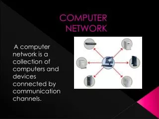
What is a LAN? Local area means: • Private ownership • freedom from regulatory constraints of WANs • Short distance (~1km) between computers • low cost • very high-speed, relatively error-free communication • complex error control unnecessary • Machines are constantly moved • Keeping track of location of computers a chore • Simply give each machine a unique address • Broadcast all messages to all machines in the LAN • Need a medium access control protocol
RAM RAM Typical LAN Structure • Transmission Medium • Network Interface Card (NIC) • Unique MAC “physical” address Ethernet Processor ROM
Medium Access Control Sublayer • In IEEE 802.1, Data Link Layer divided into: • Medium Access Control Sublayer • Coordinate access to medium • Connectionless frame transfer service • Machines identified by MAC/physical address • Broadcast frames with MAC addresses • Logical Link Control Sublayer • Between Network layer & MAC sublayer
OSI IEEE 802 Network layer Network layer 802.2 Logical link control LLC Data link layer 802.11 Wireless LAN Other LANs 802.3 CSMA-CD 802.5 Token Ring MAC Physical layer Various physical layers Physical layer MAC Sub-layer
C A Reliable frame service A Unreliable Datagram Service C LLC LLC LLC MAC MAC MAC MAC MAC MAC PHY PHY PHY PHY PHY PHY Logical Link Control Layer • IEEE 802.2: LLC enhances service provided by MAC
IP Packet IP LLC Header LLC PDU Data MAC Header FCS Encapsulation of MAC frames
IEEE 802.3 MAC: Ethernet MAC Protocol: • CSMA/CD • Slot Time is the critical system parameter • upper bound on time to detect collision • upper bound on time to acquire channel • upper bound on length of frame segment generated by collision • quantum for retransmission scheduling • max{round-trip propagation, MAC jam time} • Truncated binary exponential backoff • for retransmission n: 0 < r < 2k, where k=min(n,10) • Give up after 16 retransmissions
IEEE 802.3 Original Parameters • Transmission Rate: 10 Mbps • Min Frame: 512 bits = 64 bytes • Slot time: 512 bits/10 Mbps = 51.2 msec • 51.2 msec x 2x10⁵ km/sec =10.24 km, 1 way • 5.12 km round trip distance • Max Length: 2500 meters + 4 repeaters • Each x10 increase in bit rate, must be accompanied by x10 decrease in distance
IEEE 802.3 MAC Frame 802.3 MAC Frame 7 1 6 6 2 4 Destination address Source address Information FCS Pad Preamble Length SD Synch Start frame 64 - 1518 bytes • Every frame transmission begins “from scratch” • Preamble helps receivers synchronize their clocks to transmitter clock • 7 bytes of 10101010 generate a square wave • Start frame byte changes to 10101011 • Receivers look for change in 10 pattern
802.3 MAC Frame 7 1 6 6 2 4 Destination address Source address Information FCS Pad Preamble Length SD Synch Start frame 64 - 1518 bytes • Destination address • single address • group address • broadcast = 111...111 • Addresses • local or global • Global addresses • first 24 bits assigned to manufacturer; • next 24 bits assigned by manufacturer • Cisco 00-00-0C • 3COM 02-60-8C 0 Single address Group address 1 0 Local address 1 Global address IEEE 802.3 MAC Frame
802.3 MAC Frame 7 1 6 6 2 4 Destination address Source address Information FCS Pad Preamble Length SD Synch Start frame 64 - 1518 bytes IEEE 802.3 MAC Frame • Length: # bytes in information field • Max frame 1518 bytes, excluding preamble & SD • Max information 1500 bytes: 05DC • Pad: ensures min frame of 64 bytes • FCS: CCITT-32 CRC, covers addresses, length, information, pad fields • NIC discards frames with improper lengths or failed CRC
(b) (a) transceivers IEEE 802.3 Physical Layer Table 6.2 IEEE 802.3 10 Mbps medium alternatives Hubs & Switches! Thick Coax: Stiff, hard to work with T connectors flaky
Single collision domain High-Speed backplane or interconnection fabric (b) (a) Ethernet Hubs & Switches Twisted Pair Cheap Easy to work with Reliable Star-topology CSMA-CD Twisted Pair Cheap Bridging increases scalability Separate collision domains Full duplex operation
a = .01 a = .1 a = .2 Ethernet Scalability • CSMA-CD maximum throughput depends on normalized delay-bandwidth product a=tprop/X • x10 increase in bit rate = x10 decrease in X • To keep a constant need to either: decrease tprop (distance) by x10; or increase frame length x10
Fast Ethernet Table 6.4 IEEE 802.3 100 Mbps Ethernet medium alternatives To preserve compatibility with 10 Mbps Ethernet: • Same frame format, same interfaces, same protocols • Hub topology only with twisted pair & fiber • Bus topology & coaxial cable abandoned • Category 3 twisted pair (ordinary telephone grade) requires 4 pairs • Category 5 twisted pair requires 2 pairs (most popular) • Most prevalent LAN today
Gigabit Ethernet Table 6.3 IEEE 802.3 1 Gbps Fast Ethernet medium alternatives • Slot time increased to 512 bytes • Small frames need to be extended to 512 B • Frame bursting to allow stations to transmit burst of short frames • Frame structure preserved but CSMA-CD essentially abandoned • Extensive deployment in backbone of enterprise data networks and in server farms
10 Gigabit Ethernet Table 6.5 IEEE 802.3 10 Gbps Ethernet medium alternatives • Frame structure preserved • CSMA-CD protocol officially abandoned • LAN PHY for local network applications • WAN PHY for wide area interconnection using SONET OC-192c • Extensive deployment in metro networks anticipated
IEEE 802.5 Ring LAN • Unidirectional ring network • 4 Mbps and 16 Mbps on twisted pair • Differential Manchester line coding • Token passing protocol provides access • Fairness • Access priorities • Breaks in ring bring entire network down • Reliability by using star topology
A Wiring Center E B D C Star Topology Ring LAN • Stations connected in star fashion to wiring closet • Use existing telephone wiring • Ring implemented inside equipment box • Relays can bypass failed links or stations
Data frame format 1 1 6 4 1 1 6 1 Destination address Source address SD AC FC Information FCS ED FS J K 0 J K 0 0 0 SD AC ED M P P P T R R R J K 1 J K 1 I E Token Frame Format Token frame format J, K nondata symbols (line code) J begins as “0” but no transition K begins as “1” but no transition Starting delimiter Access control PPP=priority; T=token bit M=monitor bit; RRR=reservation T=0 token; T=1 data I = intermediate-frame bit E = error-detection bit Ending delimiter
Wireless Data Communications • Wireless communications compelling • Easy, low-cost deployment • Mobility & roaming: Access information anywhere • Supports personal devices • PDAs, laptops, data-cell-phones • Supports communicating devices • Cameras, location devices, wireless identification • Signal strength varies in space & time • Signal can be captured by snoopers • Spectrum is limited & usually regulated
C A B D Ad Hoc Communications • Temporary association of group of stations • Within range of each other • Need to exchange information • E.g. Presentation in meeting, or distributed computer game, or both
B1 A1 Gateway to the Internet Portal Distribution System Server Portal AP1 A2 B2 AP2 BSS A BSS B Infrastructure Network • Permanent Access Points provide access to Internet
C A B (b) Data Frame B C Data Frame A C transmits data frame & collides with A at B Hidden Terminal Problem (a) Data Frame A transmits data frame C senses medium, station A is hidden from C • New MAC: CSMA with Collision Avoidance
(a) B RTS C A requests to send (b) CTS B CTS A C B announces A ok to send (c) B Data Frame A sends C remains quiet CSMA with Collision Avoidance
Hub Hub Two Twisted Pairs Station Station Station Hubs, Bridges & Routers • Hub: Active central element in a star topology • Twisted Pair: inexpensive, easy to insall • Simple repeater in Ethernet LANs • “Intelligent hub”: fault isolation, net configuration, statistics • Requirements that arise: User community grows, need to interconnect hubs Hubs are for different types of LANs ? Hub Two Twisted Pairs Station Station Station
Hub Hub Two Twisted Pairs Two Twisted Pairs Station Station Station Station Station Station Hubs, Bridges & Routers • Interconnecting Hubs • Repeater: Signal regeneration • All traffic appears in both LANs • Bridge: MAC address filtering • Local traffic stays in own LAN • Routers: Internet routing • All traffic stays in own LAN Higher Scalability ?
General Bridge Issues Network Network • Operation at data link level implies capability to work with multiple network layers • However, must deal with • Difference in MAC formats • Difference in data rates; buffering; timers • Difference in maximum frame length LLC LLC MAC 802.5 MAC 802.3 802.3 802.5 802.3 802.5 802.3 802.5 PHY PHY 802.5 802.3 Token Ring CSMA/CD
Network Network Bridge LLC LLC MAC MAC MAC MAC Physical Physical Physical Physical Bridges of Same Type • Common case involves LANs of same type • Bridging is done at MAC level
S1 S2 S3 LAN1 Bridge LAN2 S6 S4 S5 Transparent Bridges • Interconnection of IEEE LANs with complete transparency • Use table lookup, and • discard frame, if source & destination in same LAN • forward frame, if source & destination in different LAN • use flooding, if destination unknown • Use backward learning to build table • observe source address of arriving LANs • handle topology changes by removing old entries
Address Port Address Port S5 S1 S2 S3 S4 LAN1 LAN2 LAN3 B1 B2 Port 1 Port 2 Port 1 Port 2
S1→S5 S5 S1 S2 S3 S4 S1 to S5 S1 to S5 S1 to S5 S1 to S5 LAN1 LAN2 LAN3 B1 B2 Port 1 Port 2 Port 1 Port 2 Address Port Address Port S1 1 S1 1
S3→S2 S5 S1 S2 S3 S4 S3S2 S3S2 S3S2 S3S2 S3S2 LAN1 LAN2 LAN3 B1 B2 Port 1 Port 2 Port 1 Port 2 Address Port Address Port S1 1 S1 1 S3 1 S3 1
S4S3 S5 S1 S2 S3 S4 S4 S3 S4S3 S4S3 LAN1 LAN2 LAN3 S4S3 B1 B2 Port 1 Port 2 Port 1 Port 2 Address Port Address Port S1 1 S1 1 S3 2 S3 1 2 2 S4 S4
Address Port S1 1 S3 1 2 S4 S2S1 S5 S1 S2 S3 S4 S2S1 S2S1 LAN1 LAN2 LAN3 B1 B2 Port 1 Port 2 Port 1 Port 2 Address Port S1 1 S3 2 2 S4 1 S2
Adaptive Learning • In a static network, tables eventually store all addresses & learning stops • In practice, stations are added & moved all the time • Introduce timer (minutes) to age each entry & force it to be relearned periodically • If frame arrives on port that differs from frame address & port in table, update immediately