Exploring Telescope Design and Resolution in Astronomy
250 likes | 296 Vues
Explore the design of modern telescopes, diffraction-limited resolution, adaptive optics, and overcoming atmospheric challenges in this lecture. Learn about Gemini North, diffraction patterns, and the Rayleigh Criterion.

Exploring Telescope Design and Resolution in Astronomy
E N D
Presentation Transcript
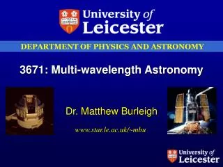
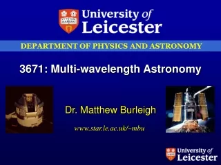
3671 Multi-Wavelength Astronomy Lecture 3: Telescopes
In this lecture we will cover: • Design of modern, large optical (& IR) telescopes • Diffraction limited resolution • Qmin=1.22l/D • Influence of atmosphere – “seeing” • Adaptive optics • Overcoming “seeing” • Magnification and plate scale
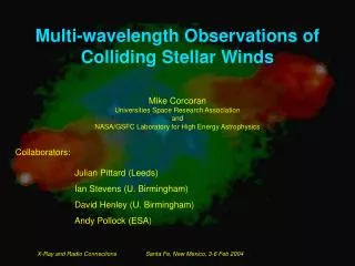
8m Gemini North on Hawaii • Opened early 2001
8m Gemini North on Hawaii • Opened early 2001
Diffraction limited resolution • A fundamental limit exists in our ability to resolve objects • This limit arises by diffraction • Consider a single slit width D • Any ray passing through this aperture and arriving at a specific point in the focal plane is associated with another ray passing through the aperture one half slit width away and arriving at the same point.
Diffraction limited resolution • If the two rays are one-half wavelength (l/2) out of phase, destructive interference occurs: • (D/2) sin q = l/2 • Or sin q = l/D • Now consider dividing the aperture into four equal segments • A ray from the edge of the opening pairs up with one passing through a point one-quarter of a slit width away • For destructive interference to occur: • (D/4) sin q = l/2 • Or sin q = 2l/D • This analysis may be continued by considering dividing the aperture into 6 segments, then 8, 10 etc • In general, for minima to occur as a result of destructive interference from light passing through a single slit • Sin q = m l/D • Where m = 1, 2, 3 … for dark fringes
Diffraction limited resolution • The analysis for light passing through a circular aperture like a telescope is more complex • Due to the symmetry of the problem, the diffraction pattern appears as concentric rings:
Diffraction limited resolution • The solution to this problem was first obtained in 1835 by Sir George Airy • The central bright spot is known as an Airy Disk, the rings as Airy Rings • A similar equation to our ideal slit describes the location of diffraction minima, but m is no longer an integer
Diffraction limited resolution • When the diffraction patterns of two sources are sufficiently close together, the diffraction rings are no longer distinguished • The two images are said to be unresolved when the central max of one image falls inside the first minimum of the other • This arbitrary resolution condition is called the Rayleigh Criterion • Assuming qmin is quite small, and invoking the small angle approximation: • qmin = 1.22 l / D • q in radians • note to convert radians to arcsecs x by 206265 • Resolution improves with increasing telescope size and at shorter wavelengths
Seeing • Unfortunately, the resolution of ground-based telescopes does not improve without limit as the mirror size increases • This is due to the turbulent nature of the Earth’s atmosphere • Local changes in atmospheric T and density over small distances create regions where the light is refracted in random directions • This causes a point source to become blurred • Since stars are effectively point sources, they twinkle • The quality of the image of a star at a given observing location and time is called “seeing” • A measure of resolution allowed by atmosphere • The best seeing at major observatories like Hawaii & La Palma can be below 0.5 arcseconds
Seeing, image size & point spread function • The light from a point source like a star spreads itself across the detector (photographic plate, CCD, etc) in a roughly circular pattern • Obviously in poor conditions or if the object is moving the image can become elongated • This is called the point spread function • A cross-section of the PSF is approximately gaussian • We measure the size of the image (PSF) in arcseconds • 1 arcsecond = 1/60 arcminute = 1/3600 degree • Human eye resolution ~1arcminute • Pair of car headlights 100km away ~1arcsecond apart • A man on the moon ~1/1000 arcsecond • Size of Betelgeuse (red giant star) ~ 1/20 arcsecond
Seeing • Betelgeuse seen with the 4m William Herschel Telescope on La Palma in about 1” seeing
Choosing an observing site • A steady atmosphere to minimise times of poor seeing • Away from sources of scattered light (ie street lights) and sources of dust (industrial areas, sandy deserts) • For infra-red astronomy, want atmospheric water vapour content as low as possible • Good weather! • Remote site • High altitude • Little rainfall • Atacama, Chile • Oceanic islands – La Palma, Hawaii • Poorer sites: Anglo-Australian Telescope • Best site – Space!! (HST)
HST + WFPC 2 • HST / WFPC2 image of a multiple star system including a white dwarf • Aa (solar-like star) – Ab (white dwarf) = 0.4” • Image made in ultraviolet at 170nm • Diffraction limited resolution of HST (2.4m) = 0.02” • In reality, resolution is more like 0.08”. Why?
Adaptive optics • Advanced computers and new technologies now allow astronomers to compensate for the effects of seeing in real time • It’s called Adaptive Optics • First AO systems designed by the military for use with spy satellites (and their own ground-based telescopes!) • 1990s declassified material plus efforts within astronomical community has led to AO systems being installed at world’s major observatories • Only now becoming really effective • AO system consists of 3 principle components • A deformable mirror (wavefront corrector) • A wavefront sensor • Control system (real-time computer)
The wave front sensor • Estimates the distortion of the atmosphere along the line-of-sight to the target • Requires a bright source near the target • either a star (Gemini telescopes need stars brighter than 13th mag) • Or a fake star created by a laser • Laser stimulates sodium atoms in a layer at an altitude of about 90km
The control system • Calculates the corrections required based on inputs from the wave front sensor • Commands the actuators which deform the mirror • Calculations are performed in sub-millisecond range to keep up with changing atmosphere
The deformable mirror • Piezoelectric actuators deform the mirror • The number of actuators required for near-perfect corrections in the optical is several thousand – unrealistic • AO works best in the IR, where fewer actuators are required
Quantifying AO performance • The Freid parameter, r0 • A measure of atmospheric turbulence • r0decreases as turbulence increases • Also, r0is proportional to l**6/5 • r0can be viewed as the size of a telescope that would give the same resolution as the atmospheric seeing • So if seeing = 1”, r0= 10cm in the optical (using l/D) • i.e. r0 = l / seeing in radians • Since r0 l-dependent, then if r0 = 10cm at 550nm it would be 70cm at 3.4 microns in the IR • So it is easier to perform AO in the IR than in the optical
Quantifying AO performance • The Strehl ratio R is the ratio of the quality of the image obtained to that of a theoretically perfect point source image (Airy disk) • R is proportional to r0 and R improves (ie the image quality improves) with larger r0 • 0 < R < 1; R=1 is a perfect image • For detection of extra-solar planets, need R>0.9 • As R increases, most of the light is concentrated in the central core and little in the Airy rings • Of course, R is l-dependent • e.g. an AO system that gives an R of say 0.9 in the IR will only give 0.1-0.2 in the visual
AO at the USAF Starfire facility Binary Kappa Peg: 3D plot: uncompensated and with full AO (right) Uncompensated on 1.5m telescope 756-actuators: 0.3” resolution
AO on Gemini North Globular cluster NGC6934 observed with the 8m Gemini North telescope on Hawaii, in the visible (left) and in the IR (right) with the Hokopu’a AO system
Magnification, resolution and plate scale • If F= focal length (mm) and D = diameter of telescope, then focal ratio f=F/D • If q=angular resolution in arcsecs then • Image size s = F tan q or Fq assuming small angles • An increase in focal length increases the scale of a pattern, but not the resolution • Magnification – changes the size of an image • Resolution – necessary to increase D to see more detail • Plate scale – no. of arcsec per mm in image plane • Plate scale dq/ds = 1/F = 206265 / fD • Rem. 206265 arcsecs/radian
Telescopes: summary • After this lecture you should know and understand • The definition of diffraction limited resolution • q = 1.22l/D • The limitations imposed by atmospheric seeing • Overcoming seeing with Adaptive Optics • Definition of Fried parameter and Strehl ratio • Definitions of image size magnification and plate scale