Omnidirectional Drive Systems Kinematics and Control
Omnidirectional Drive Systems Kinematics and Control Presented by: Andy Baker President, AndyMark, Inc., FRC 45 Ian Mackenzie Master’s Student, Univ. of Waterloo, FRC 1114 Who? Andy Baker FRC mentor since 1998 (FRC 45, TechnoKats) Designer of gearboxes, wheels, etc.

Omnidirectional Drive Systems Kinematics and Control
E N D
Presentation Transcript
Omnidirectional Drive SystemsKinematics and Control Presented by: Andy Baker President, AndyMark, Inc., FRC 45 Ian Mackenzie Master’s Student, Univ. of Waterloo, FRC 1114 2008 FIRST Robotics Conference
Who? • Andy Baker • FRC mentor since 1998 (FRC 45, TechnoKats) • Designer of gearboxes, wheels, etc. • Started AndyMark in 2004 • Inspector, referee, 2003 WFA winner • Ian Mackenzie • FRC student: 1998-2002 (FRC 188, Woburn) • FRC mentor since 2004 (FRC 1114, Simbotics) • Waterloo Regional planning committee • 2008 Waterloo Regional WFFA winner 2008 FIRST Robotics Conference
Outline • Drive intro • Drive types • Kinematics • Examples 2008 FIRST Robotics Conference
Drive Types • Tank drive: 2 degrees of freedom • Omni-directional drive: 3 degrees of freedom 2008 FIRST Robotics Conference
Omni-directional Drive History • 1998: crab steering, FRC team 47 • 1998: Omni wheels, FRC team 67, 45 • 2002: 3-wheel Killough drive, FRC team 857 • 2003: Ball Drive, FRC team 45 • 2005: Mecanum-style “Jester Drive”, FRC team 357 • 2005: AndyMark, Inc. sells “Trick Wheels” • 2007: AndyMark, Inc. sells Mecanum wheels 2008 FIRST Robotics Conference
Strategy Primarily offensive robots Not good at pushing Good at avoiding defense Confined spaces on the field Raising the Bar in 2004 Analogous to industrial applications Inspirational and innovative
Omni-directional Drive Types • Swerve (or Crab) Drive • Killough Drive, using omni-wheels • Mecanum Drive • Ball Drive 2008 FIRST Robotics Conference
Swerve Drive • High-traction wheels • Each wheel rotates to steer + No friction losses in wheel-floor interface + Ability to push or hold position is high + Simple wheels • Complex system to control and program • Mechanical and control issues • Difficult to drive • Wheel turning delay 2008 FIRST Robotics Conference
Swerve drive pictures 2008 FIRST Robotics Conference
Holonomic Stephen Killough, 1994 + Simple Mechanics + Immediate Turning + Simple Control – 4 wheel independent No brake Minimal pushing power Jittery ride, unless using dualies Incline difficulty
Mecanum drive + Simple mechanisms + Immediate turn + Simple control – 4 wheel independent Minimal brake OK pushing power Needs a suspension Difficulty on inclines
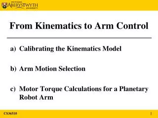
Kinematics Mathematics describing motion Solid grasp of theory makes control much easier Great example of how real university-level theory can be applied to FIRST robots Three-step process: Define overall robot motion Usually by translation velocity , rotational velocity Calculate velocity at each wheel Calculate actual wheel speed (and possibly wheel orientation) from each wheel’s velocity
Overall Robot Motion Break robot motion down into (translational velocity of the center of the robot) and (rotational velocity) and express as scalar components is forward-back motion (positive forward) is sideways motion (positive to the right) is angular speed (positive counter-clockwise)
Overall Robot Motion Examples Drive forward: Spin in place counterclockwise: Drive forward while turning to the right: ‘Circle strafe’ to the right:
Defining Robot Motion How to get , , ? A few ideas… Joystick + knob: Y and X axes of joystick give and , knob twist gives Direct but not very intuitive to use Two joysticks, crab priority: Y and X axes of first joystick give and , -X axis of second joystick gives Normally drive in crab mode, moving second joystick adds rotation motion (like playing a first-person computer game with arrow keys and a mouse) Two joysticks, tank priority: Y and –X axes of first joystick give and , X axis of second joystick gives Normally drive in tank mode, moving second joystick adds sideways motion (‘strafing’ or ‘dekeing’)
Velocity at a Point Common to all types of omnidirectional drive Given (translational velocity of the center of the robot) and , determine the velocity of some other point on the robot (e.g., the velocity at a particular wheel) Once the velocity at a wheel is known, we can calculate the speed at which to turn that wheel (and possibly the orientation of that wheel)
Velocity at a Point is a vector giving the position of a point on the robot (e.g., the position of a wheel) relative to the center of the robot Vector approach: Scalar approach:
Velocities of Multiple Points In general, each wheel will have a unique speed and direction Full swerve drive would require at least 8 motors; has been done once (Chief Delphi in 2001) Swerve drive usually done with 2 swerve modules along with casters or holonomic wheels
Swerve Drive Resolve velocity at each wheel into magnitude (wheel speed) and angle (steering angle) Note that is a translational speed (e.g., ft/s) and will have to be transformed into a rotational speed (e.g., wheel RPM) Be careful with angle quadrants!
Holonomic Drive Resolve velocity into parallel and perpendicular components; magnitude of parallel component is wheel speed is a unit vector in the direction of the wheel (whichever direction is assumed to be forwards)
Mecanum Drive Similar to holonomic drive Conceptually: Resolve velocity into components parallel to wheel and parallel to roller Not easy to calculate directly (directions are not perpendicular), so do it in two steps
Resolve to Roller Resolve velocity into components parallel and perpendicular to roller axis is not the same for each wheel; pick direction parallel to roller axis, in forwards direction Perpendicular component can be discarded
Resolve to Wheel Use component parallel to roller axis and resolve it into components parallel to wheel and parallel to roller The component parallel to the wheel is In this case, the angle is known, so we can calculate directly:
Mecanum Drive Example Using wheel 3 as an example:
Mecanum Drive Example Similarly,Note that all speeds are linear functions of the inputs (i.e., no trigonometry or square roots necessary)
Hybrid Swerve/Holonomic Drive Swerve module 1:
Hybrid Swerve/Holonomic Drive Swerve module 2:
Hybrid Swerve/Holonomic Drive Holonomic wheel:
Scaling Issues Speed calculations may result in greater-than-maximum speeds Possible to limit inputs so this never happens, but this overly restricts some directions Better to adjust speeds on the fly
Scaling Algorithm Calculate wheel speeds for each wheel Find maximum wheel speed If this is greater than the maximum possible wheel speed, calculate the scaling factor necessary to reduce it to the maximum possible wheel speed Scale all wheel speeds by this factor
Questions? andyb@andymark.biz ian.e.mackenzie@gmail.com