BIONIC EYE
BIONIC EYE. A Look into Current Research and Future Prospects. Blindness. Inability to see. Causes of Blindness. Damage to: Clear Structures in the eye, that allow the light to pass through The nerves within the eye Optic Nerve Brain. Bradley’s Research . Breakthrough in 1960


BIONIC EYE
E N D
Presentation Transcript
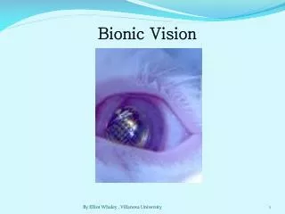
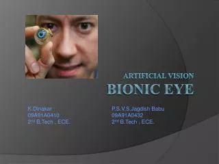
BIONIC EYE A Look into Current Research and Future Prospects
Blindness Inability to see
Causes of Blindness Damage to: • Clear Structures in the eye, that allow the light to pass through • The nerves within the eye • Optic Nerve • Brain
Bradley’s Research • Breakthrough in 1960 • First electrical stimulation of Visual Cortex • Bright spots called phosphenes produced
Why we should be optimistic? The Success of : • Cardiac pacemakers as neural prosthesis • Cochlear implants to restore hearing to the deaf Rapid developments in : • VLSI design • Micro- fabrication technology
Overview • Biology of the Eye • MIT – Harvard Device • ASR – Artificial Silicon Retina • MARC – Multiple Unit Artificial Retina Chip Set System
BIONIC EYE ? • Bio-electronic eye • Electronic device which replaces functionality of a part or whole of the eye • Used for replacing functionality (or) • Adding functionality to the eye
Diseases of the Eye • Retinitis Pigmentosa • Macular Degeneration
Retinitis Pigmentosa • Hereditary Genetic Disease • Peripheral Rods degenerate • Gradually progresses towards center of eye • Spares the foveal region • Tunnel vision results
Macular Degeration • Genetically Related • Cones in Macula region degenrate • Loss or damage of central vision • Peripheral Retina spared • Common among old people
Retinitis Pigmentosa( Opthalmoscope View) NORMAL EYE DEFECTIVE EYE
Macular Degeneration(Opthalmoscope View) NORMAL EYE DEFECTIVE EYE
Regions of Implantation • Retina • Optic Nerve • Lateral geniculate body • Visual Cortex
MIT-Harvard device Features • Epi-Retinal Approach • Microelectrode array replaces damaged photoreceptors • Power source – Laser(820nm wavelength) • Image Acquisition - Using CCD Camera • Patient spectacle holds the camera and power source
Implant Structure • Layers 1- Photodiode Array 2- Polyimide strip 3- Stimulator chip • Electrodes on other end of Polyimide strip
Working of the System - 1 • CCD camera input – External light intensity • CCD output amplitude-modulates laser source • This hits photodiode array of implant • This in turn powers stimulator chip (SC)
Working of the System - 2 • SC drives current to electrodes facing retina • This excites the ganglionic cells > axons > optic nerve > visual cortex in occipital lobe of brain • Brain helps in perceiving an image
Advantages • Very Early in the visual pathway • No Batteries implanted within body • No complicated surgical procedure • Power Requirement – ¼ of milliwatt
Disadvantages • Axons b/w electrodes and ganglionic cells • Other axons get excited – unwanted perception of large blur • Extra circuitry required for downstream electrical input
Artificial Retina Prosthesis using ASR (Artificial Silicon Retina)
The Eye • Human Eye is similar to a camera • Macula provides the highest resolution of the image which we see. • Macula is comprised of multiple layers of cells which process the initial “analog”light energy entering the eye into “digital” electrochemical impulses. • Human eye has nearly 100 million photoreceptors.
Need for ASR • Retinitis Pigmentosa(RP) and Age related Macular degeneration (ARMD) are Progressive blinding disorders of the outer retina which involve degeneration of the neurons. • There are no proven effective therapeutic remedy for these disorders . • Some of Methods employed to slow or halt the disease time course are • Use of Intravitreal injection of certain growth factors. • Identification of specific gene mutations has led to the development of the gene therapy approaches. • Transplantation can be effective in rescuing the photoreceptors from degeneration.
Need for ASR • The first two methods are promising for treating patients early in the course of the degenerative process, they are of relatively modest value for the patients in whom the photoreceptors have already degenerated. • Besides the Genetic and the Anatomic approach , there is an need to find an alternative approach.
Fundamental idea behind ASR • ASR is a solid state biocompatible chip which contains an array of photo receptors ,and is implanted to replace the functionality of the defective photoreceptors . • Current generated by the device in response to light stimulation will alter the membrane potential of the overlying neurons and thereby activate the visual system. • Visual sensations or “phosphenes” can be evoked by electrical stimulation of the different levels of the visual pathway. • Phosphenes are evoked by the stimulation of the eyeball or the visual cortex. • Artificial vision created by the controlled electric stimulation of the retina has color.
Approaches Towards Retinal Prosthetic Implantation • Epiretinal Approach involves a semiconductor based device positioned on the surface of the retina to try to simulate the remaining overlying cells of the retina. • Subretinal Approach involves implanting the ASR chip behind the retina to simulate the remaining viable cells.
Limitations Of ASR’s • ASR is designed to interface and function with the retina that has partial outer retinal degeneration. • ASR can be applied only when the photoreceptor cellular layer of the retina is damaged but the remaining cellular layers are still functional. • ASR can be effectively applied to RP and AMD. • Conditions amenable to treatment with ASR’s include some forms of long-term retinal detachment,Usher’s syndrome, Cone- Rod Dystrophy.
Sub-Retinal Approach • The basic idea-”Alter the membrane potential” • IMPLANT DESIGN • Primitive devices • Single photosensitive pixel(3mm in diameter) • Neo devices • The current micro photodiode array (MPA) is comprised of a regular array of individual photodiode subunits, each approximately 20×20-µm square and separated by 10-µm channel stops (37). The resulting micro photodiode density is approximately 1,100/m2.
IMPLANT features • The size has decreased from 250um to 50um • No external power supply • 500nm to 1100nm wavelength response
MANUFACTURING PROCESS • Implants are comprised of a doped and ion-implanted silicon substrate disk to produce a PiN (positive-intrinsic-negative) junction. Fabrication begins with a 7.6-cm diameter semiconductor grade N-type silicon wafer. • For the MPA device, a photomask is used to ion-implant shallow P+ doped wells into the front surface of the wafer, separated by channel stops in a pattern of individual micro photodiodes. An intrinsic layer automatically forms at the boundary between the P+-doped wells and the N-type substrate of the wafer.
PROCESS (Contd.) • The back of the wafer is then ion-implanted to produce a N+ surface. Thereafter, an insulating layer of silicon nitrate is deposited on the front of the wafer, covering the entire surface except for the well openings. • A thin adhesion layer, of chromium or titanium, is then deposited over the P+ and N+ layers. A transparent electrode layer of gold, iridium/iridium oxide, or platinum, is deposited on the front well side, and on the back ground side. • In its simplest form, the photodiode and electrode layers are the same size. However, the current density available at each individual micro photodiode subunit can be increased by increasing the photodiode collector to electrode area ratio.
Post Implant function and Inference • Measurement procedure • IR stimulation at 940nm on the ASR chip • Recorded at the corneal surface using contact lens electrode • Comparison of responses of gold, platinum and iridium electrodes • Iridium based device has a longer persistence • Stability of these electrodes
BIO-COMPATIBILTY results • The good news • There is no progressive change in retinal appearance that may be associated with retinal toxicity. • How do we know? ----”ERG and Ganzfeld stimulus has an answer” • The Bad news • Loss of photoreceptive layer over the region of implant which is expected due to deprival of oxygen and nutrients to those cells underlying the chip.
10x10 Stimulator Chip With Telemetry Decoding 10x10 Stimulator Chip With Telemetry Decoding
Advantages of MARC system • Compact Size – 6x6 mm • Diagnostic Capability • Reduction of stress upon retina