Multiple Access
Multiple Access. ECS 152A. Concepts. Multiple access vs. multiplexing Multiplexing allows several transmission sources to share a larger transmission capacity. Often used in hierarchical structures.

Multiple Access
E N D
Presentation Transcript
Multiple Access ECS 152A
Concepts • Multiple access vs. multiplexing • Multiplexing allows several transmission sources to share a larger transmission capacity. Often used in hierarchical structures. • Multiple access: two or more simultaneous transmissions share a broadcast channel. Often used in access networks • sometimes interchangeable • Bandwidth (bps) vs. bandwidth (Hz) • bps: data rate • Hz: frequency in physical carrier
Multiple Access protocols • Point-to-point vs. broadcast channel • Broadcast link can have multiple sending and receiving nodes all connected to the same, single, shared broadcast channel. • single shared broadcast channel • two or more simultaneous transmissions by nodes: interference • collision if node receives two or more signals at the same time multiple access protocol • distributed algorithm that determines how nodes share channel, i.e., determine when node can transmit • communication about channel sharing must use channel itself! • no out-of-band channel for coordination
Ideal Multiple Access Protocol Broadcast channel of rate R bps 1. When one node wants to transmit, it can send at rate R. 2. When M nodes want to transmit, each can send at average rate R/M 3. Fully decentralized: • no special node to coordinate transmissions • no synchronization of clocks, slots 4. Simple
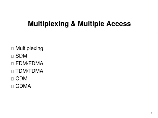
MAC Protocols: a taxonomy Three broad classes: • Channel Partitioning • divide channel into smaller “pieces” (time slots, frequency, code) • allocate piece to node for exclusive use • Random Access • channel not divided, allow collisions • “recover” from collisions • “Taking turns” • Nodes take turns, but nodes with more to send can take longer turns
Channel Partitioning MAC protocols: FDMA FDMA: frequency division multiple access • channel spectrum divided into frequency bands • each station assigned fixed frequency band • unused transmission time in frequency bands go idle • example: 6-station LAN, 1,3,4 have pkt, frequency bands 2,5,6 idle • TDM (Time Division Multiplexing): channel divided into N time slots, one per user; inefficient with low duty cycle users and at light load. • FDM (Frequency Division Multiplexing): frequency subdivided. time frequency bands
FDMA: example • AMPS (Advanced Mobile Phone System) • The first cellular system in US • Forward link 869-894 MHz • Reverse link 824-847 MHz • Example: An operator with 12.5MHz in each simplex band. Bg is the guard band allocated at the edge of the allocated spectrum band. Bc is the channel bandwidth. • Bg=10KHz • Bc=30kHz • N= (12.5M-2x10K)/30K =416 simultaneous users!
Channel Partitioning MAC protocols: TDMA TDMA: time division multiple access • access to channel in "rounds" • each station gets fixed length slot (length = pkt trans time) in each round • unused slots go idle • example: 6-station LAN, 1,3,4 have pkt, slots 2,5,6 idle • TDM (Time Division Multiplexing): channel divided into N time slots, one per user; inefficient with low duty cycle users and at light load. • FDM (Frequency Division Multiplexing): frequency subdivided.
Example • GSM
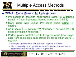
Code Division Multiple Access (CDMA) • used in several wireless broadcast channels (cellular, satellite, etc) standards • unique “code” assigned to each user; i.e., code set partitioning • all users share same frequency, but each user has own “chipping” sequence (i.e., code) to encode data • encoded signal = (original data) X (chipping sequence) • decoding: inner-product of encoded signal and chipping sequence • allows multiple users to “coexist” and transmit simultaneously with minimal interference (if codes are “orthogonal”)
d0 = 1 1 1 1 1 1 1 d1 = -1 1 1 1 1 1 1 1 1 1 1 1 1 1 1 1 1 1 1 1 1 1 1 1 1 1 1 - - - - - - - - - - - - - - - - - - - - - - - - - - - - - - - - 1 1 1 1 1 1 1 1 1 1 1 1 1 1 1 1 1 1 1 1 1 1 1 1 1 1 1 1 1 1 1 1 M Di = SZi,m.cm m=1 M d0 = 1 d1 = -1 CDMA Encode/Decode channel output Zi,m Zi,m= di.cm data bits sender slot 0 channel output slot 1 channel output code slot 1 slot 0 received input slot 0 channel output slot 1 channel output code receiver slot 1 slot 0
(a) (b) A A A A Trunk group B B B MUX MUX B C C C C Multiplexing • Sharing network resources • Bandwidth, router buffer • The cost of deploying high bandwidth transmission line is more economical • Exploit the statistical behavior of users
(a) Individual signals occupy W Hz A f W 0 B 0 f W C B A f C f 0 W (b) Combined signal fits into channel bandwidth Frequency Division Multiplexing • The bandwidth is divided into frequency slots • Each frequency slot is allocated to a different user • FDM was first introduced in the telephone network • Other examples – broadcast radio and cable television
Frequency Division Multiplexing • Useful bandwidth of medium exceeds required bandwidth of channel • Each signal is modulated to a different carrier frequency • Carrier frequencies separated so signals do not overlap (guard bands) • e.g. broadcast radio • Channel allocated even if no data
Analog Carrier Systems • AT&T (USA) • Hierarchy of FDM schemes • Group • 12 voice channels (4kHz each) = 48kHz • Range 60kHz to 108kHz • Supergroup • 60 channel • FDM of 5 group signals on carriers between 420kHz and 612 kHz • Mastergroup • 10 supergroups
(a) Each signal transmits 1 unit every 3T seconds A1 A2 t 0T 6T 3T B1 B2 t 6T 3T 0T C1 C2 t 0T 6T 3T (b) Combined signal transmits 1 unit every T seconds A2 B2 B1 C1 C2 A1 t 0T 1T 2T 3T 4T 5T 6T Time Division Multiplexing • Separate bit streams are multiplexed into a high-speed digital transmission line • Transmission is carried out in terms of frames which are composed of equal sized slots which are assigned to users • Demultiplexing is done by reading the data in the appropriate slot in each frame
DS1 Low-Speed Mapping Function DS2 STS-1 CEPT-1 51.84 Mbps DS3 Medium Speed Mapping Function STS-1 44.736 OC-n STS-n STS-3c STS-1 Mux E/O Scrambler CEPT-4 High- Speed Mapping Function STS-1 STS-1 139.264 STS-3c STS-1 STS-1 High- Speed Mapping Function ATM STS-1 150 Mbps SONET Digital Hierarchy
Statistical TDM • In Synchronous TDM many slots are wasted • Statistical TDM allocates time slots dynamically based on demand • Multiplexer scans input lines and collects data until frame full • Data rate on line lower than aggregate rates of input lines
Optical MUX Optical deMUX 1 1 2 1 2 2. m Optical fiber m m Wave Division Multiplexing • Optical-domain version of FDM • Different information signals are modulated to different wavelengths and the combined signals sent through the fiber • Prism and difffraction gratings are used to combine/split signals
Wavelength Division Multiplexing • Multiple beams of light at different frequency • Carried by optical fiber • A form of FDM • Each color of light (wavelength) carries separate data channel • 1997 Bell Labs • 100 beams • Each at 10 Gbps • Giving 1 terabit per second (Tbps) • Commercial systems of 160 channels of 10 Gbps now available • Lab systems (Alcatel) 256 channels at 39.8 Gbps each • 10.1 Tbps and Over 100km
WDM Operation • Same general architecture as other FDM • Number of sources generating laser beams at different frequencies • Multiplexer consolidates sources for transmission over single fiber • Optical amplifiers amplify all wavelengths • Typically tens of km apart • Demux separates channels at the destination • Mostly 1550nm wavelength range • Was 200MHz per channel • Now 50GHz
Dense Wavelength Division Multiplexing • DWDM • No official or standard definition • Implies more channels more closely spaced that WDM • 200GHz or less
Random Access Protocols • When node has packet to send • transmit at full channel data rate R. • no a priori coordination among nodes • two or more transmitting nodes “collision”, • random access MAC protocol specifies: • how to detect collisions • how to recover from collisions (e.g., via delayed retransmissions) • Examples of random access MAC protocols: • slotted ALOHA • ALOHA • CSMA, CSMA/CD, CSMA/CA
Assumptions all frames same size time is divided into equal size slots, time to transmit 1 frame nodes start to transmit frames only at beginning of slots nodes are synchronized if 2 or more nodes transmit in slot, all nodes detect collision Operation when node obtains fresh frame, it transmits in next slot no collision, node can send new frame in next slot if collision, node retransmits frame in each subsequent slot with prob. p until success Slotted ALOHA
Pros single active node can continuously transmit at full rate of channel highly decentralized: only slots in nodes need to be in sync simple Cons collisions, wasting slots idle slots nodes may be able to detect collision in less than time to transmit packet clock synchronization Slotted ALOHA
Suppose N nodes with many frames to send, each transmits in slot with probability p prob that node 1 has success in a slot = p(1-p)N-1 prob that any node has a success = Np(1-p)N-1 For max efficiency with N nodes, find p* that maximizes Np(1-p)N-1 For many nodes, take limit of Np*(1-p*)N-1 as N goes to infinity, gives 1/e = .37 Slotted Aloha efficiency Efficiency is the long-run fraction of successful slots when there are many nodes, each with many frames to send At best: channel used for useful transmissions 37% of time!
Pure (unslotted) ALOHA • unslotted Aloha: simpler, no synchronization • when frame first arrives • transmit immediately • collision probability increases: • frame sent at t0 collides with other frames sent in [t0-1,t0+1]
Pure Aloha efficiency P(success by given node) = P(node transmits) . P(no other node transmits in [p0-1,p0] . P(no other node transmits in [p0-1,p0] = p . (1-p)N-1 . (1-p)N-1 = p . (1-p)2(N-1) … choosing optimum p and then letting n -> infty ... = 1/(2e) = .18 Even worse !
CSMA (Carrier Sense Multiple Access) CSMA: listen before transmit: If channel sensed idle: transmit entire frame • If channel sensed busy, defer transmission • Human analogy: don’t interrupt others!
CSMA collisions spatial layout of nodes collisions can still occur: propagation delay means two nodes may not hear each other’s transmission collision: entire packet transmission time wasted note: role of distance & propagation delay in determining collision probability
CSMA/CD (Collision Detection) CSMA/CD: carrier sensing, deferral as in CSMA • collisions detected within short time • colliding transmissions aborted, reducing channel wastage • collision detection: • easy in wired LANs: measure signal strengths, compare transmitted, received signals • difficult in wireless LANs: receiver shut off while transmitting • human analogy: the polite conversationalist
“Taking Turns” MAC protocols channel partitioning MAC protocols: • share channel efficiently and fairly at high load • inefficient at low load: delay in channel access, 1/N bandwidth allocated even if only 1 active node! Random access MAC protocols • efficient at low load: single node can fully utilize channel • high load: collision overhead “taking turns” protocols look for best of both worlds!
“Taking Turns” MAC protocols Token passing: • control token passed from one node to next sequentially. • token message • concerns: • token overhead • latency • single point of failure (token) Polling: • master node “invites” slave nodes to transmit in turn • concerns: • polling overhead • latency • single point of failure (master)
Summary of MAC protocols • What do you do with a shared media? • Channel Partitioning, by time, frequency or code • Time Division, Frequency Division • Random partitioning (dynamic), • ALOHA, S-ALOHA, CSMA, CSMA/CD • carrier sensing: easy in some technologies (wire), hard in others (wireless) • CSMA/CD used in Ethernet • CSMA/CA used in 802.11 • Taking Turns • polling from a central site, token passing