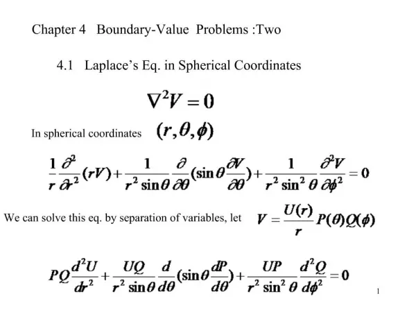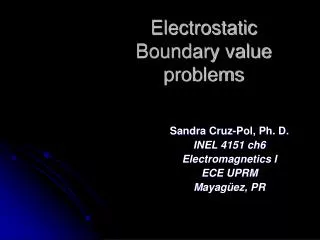
Electrostatic Boundary-Value Problems
Electrostatic Boundary-Value Problems. 1. Figure 6.1 An electrohydrodynamic pump; for Example 6.1. Figure 6.2 For Example 6.2. Figure 6.3 Potential V ( f ) due to semi-infinite conducting planes. Figure 6.4 For Practice Exercise 6.3.

Electrostatic Boundary-Value Problems
E N D
Presentation Transcript
Figure 6.1 An electrohydrodynamic pump; for Example 6.1. Elements of Electromagnetics Fourth Edition Sadiku
Figure 6.2 For Example 6.2. Elements of Electromagnetics Fourth Edition Sadiku
Figure 6.3 Potential V(f) due to semi-infinite conducting planes. Elements of Electromagnetics Fourth Edition Sadiku
Figure 6.4 For Practice Exercise 6.3. Elements of Electromagnetics Fourth Edition Sadiku
Figure 6.5 Potential V(q) due to conducting cones. Elements of Electromagnetics Fourth Edition Sadiku
Figure 6.6 For Practice Exercise 6.4. Elements of Electromagnetics Fourth Edition Sadiku
Figure 6.7 Potential V(x, y) due to a conducting rectangular trough; for Example 6.5. Elements of Electromagnetics Fourth Edition Sadiku
Figure 6.8 Sketch of cosh x andsinh x showing that sinh x =0 if and only if x =0; for Case 2 of Example 6.5. Elements of Electromagnetics Fourth Edition Sadiku
Figure 6.9 Sketch of sin xshowing that sin x = 0 at infinite number of points; for Case 3 of Example 6.5. Elements of Electromagnetics Fourth Edition Sadiku
Figure 6.10 For Example 6.5: (a) V(x, y) calculated at some points, (b) sketch of flux lines and equipotential lines. Elements of Electromagnetics Fourth Edition Sadiku
Figure 6.11 Matlab program for Example 6.5. Elements of Electromagnetics Fourth Edition Sadiku
Figure 6.12 A two-conductor capacitor. Elements of Electromagnetics Fourth Edition Sadiku
Figure 6.13 (a) Parallel-plate capacitor. (b) Fringing effect due to a parallel-plate capacitor. Elements of Electromagnetics Fourth Edition Sadiku
Figure 6.14 A coaxial capacitor. Elements of Electromagnetics Fourth Edition Sadiku
Figure 6.15 A spherical capacitor. Elements of Electromagnetics Fourth Edition Sadiku
Figure 6.16 Capacitors (a) in series and (b) in parallel. Elements of Electromagnetics Fourth Edition Sadiku
Figure 6.17 Bent metal bar for Example 6.8. Elements of Electromagnetics Fourth Edition Sadiku
Figure 6.18 Potential V(r) due to conducting spherical shells. Elements of Electromagnetics Fourth Edition Sadiku
Figure 6.19 For Practice Exercises 6.9, 6.10, and 6.12. Elements of Electromagnetics Fourth Edition Sadiku
Figure 6.20 For Example 6.12. Elements of Electromagnetics Fourth Edition Sadiku
Figure 6.21 Image system: (a) charge configurations above a perfectly conducting plane, (b) image configuration with the conducting plane replaced by equipotential surface. Elements of Electromagnetics Fourth Edition Sadiku
Figure 6.22 (a) Point charge and grounded conducting plane. (b) Image configuration and field lines. Elements of Electromagnetics Fourth Edition Sadiku
Figure 6.23 Point charge between two semi-infinite conducting planes. Elements of Electromagnetics Fourth Edition Sadiku
Figure 6.24 Determining (a) the potential at P and (b) the force on charge Q. Elements of Electromagnetics Fourth Edition Sadiku
Figure 6.25 Point charge between two semi-infinite conducting walls inclined at f = 60° to each other. Elements of Electromagnetics Fourth Edition Sadiku
Figure 6.26 Circular microstrip capacitor. Elements of Electromagnetics Fourth Edition Sadiku
Figure 6.27 Capacitance of the circular microstrip capacitor. Elements of Electromagnetics Fourth Edition Sadiku
Figure 6.28 For Problem 6.11. Elements of Electromagnetics Fourth Edition Sadiku
Figure 6.29 Cylindrical capacitor of Problem 6.12. Elements of Electromagnetics Fourth Edition Sadiku
Figure 6.30 Conducting cones of Problem 6.15. Elements of Electromagnetics Fourth Edition Sadiku
Figure 6.31 For Problem 6.18. Elements of Electromagnetics Fourth Edition Sadiku
Figure 6.32 For Problem 6.19. Elements of Electromagnetics Fourth Edition Sadiku
Figure 6.33 For Problem 6.20. Elements of Electromagnetics Fourth Edition Sadiku
Figure 6.34 For Problem 6.24. Elements of Electromagnetics Fourth Edition Sadiku
Figure 6.35 For Problem 6.26. Elements of Electromagnetics Fourth Edition Sadiku
Figure 6.36 For Problem 6.28. Elements of Electromagnetics Fourth Edition Sadiku
Figure 6.37 For Problem 6.29. Elements of Electromagnetics Fourth Edition Sadiku
Figure 6.38 For Problem 6.30. Elements of Electromagnetics Fourth Edition Sadiku
Figure 6.39 For Problem 6.32. Elements of Electromagnetics Fourth Edition Sadiku
Figure 6.40 Simplified geometry of an ink-jet printer; for Problem 6.41. Elements of Electromagnetics Fourth Edition Sadiku
Figure 6.41 For Problem 6.43. Elements of Electromagnetics Fourth Edition Sadiku