Download
1 / 77
770 likes | 951 Vues
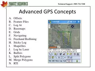
Advanced GPS Concepts. Offsets Feature Files Log At Basemaps Grids Navigating Freehand Redlining Sticky Log Shapefiles Log by Laser Buffers Split Polygons Merge Polygons RTI. A. Offsetting GPS Points.

E N D
Advanced GPS Concepts • Offsets • Feature Files • Log At • Basemaps • Grids • Navigating • Freehand Redlining • Sticky Log • Shapefiles • Log by Laser • Buffers • Split Polygons • Merge Polygons • RTI
A. Offsetting GPS Points One of the strengths of Solo Forest is the ability to easily offset any point that you are collecting. This comes in handy when it is difficult to physically get to a corner because it is grown up or on the other side of a huge ditch. Also, if your corner is a large tree, it is faster and more accurate to stand 5-10 feet from that tree and offset a point instead of collecting multipath data. • To Offset a Point, • 1. Check the Prompt for Offset Box on either tab of the Static Point logging screen. • 2. When you have enough points logged and the Deviation is acceptable, click Log Now. • 3. Next enter the correct Azimuth (from your compass) and Distance on the Point Offset Screen and then press OK.
Offsetting Lines and Areas You can also Offset Lines and Areas in Solo Forest. This feature allows you to map a stand boundary without having to walk exactly on the boundary. It is much faster and more accurate GPS-wise, to walk in a fire lane, pasture, road, clearcut, etc. instead of on the exact boundary. • To Offset a Line or Area, • Select Log > Log Offset / Interval > Log by Interval / Offset… • Select which side of you the line or area will be offset (ie. You are the line). • Double click then enter the Offset distance and press OK. • Lastly, either go to the feature list under All and start a new line or area, or select the correct feature on the In Progress screen and start logging in the Log Dynamically screen
Using the Measuring Toolto Calculate Bearings The measure tool will allow you to measure distances or bearings between points just as we measured distance. This can be done by selecting Tool > Measure Tool > Bearings. Then after selecting the Measure tool, the bearings will be calculated as you select points. This tool will also work if you have your Stylus set for Manual XY.
B. Editing the Feature File It is very easy to Edit or Add features to the feature file in Solo Forest. To do this, select File > Feature Codes. You can change the order of the features by highlighting one and clicking the Up or Down arrows, You can see the Attributes under a feature by double clicking the feature, clicking the + sign beside it. To Add a new Feature, 1. click New
Editing the Feature File • Enter the Feature name and select the type. • Click Display to edit the display settings of the new feature. Click OK. • To Add an attribute to your new feature, click Add. (Note: you have to have at least one attribute)
Editing the Feature File • Enter the Attribute name and Type. Don’t forget the Attribute asks the question. We will create a dropdown menu here. Click Next. • Click Add Menu Item… to create the Value that answers the Attribute question. Enter the Value name (Inactive) and click Add. • Repeat this process to enter all of the values and even subvalues for this attribute. Click Finish.
Editing the Feature File • Click Add again to add another Attribute to your new feature, or click OK if you only want one. • Note that the new feature is added to your list and will be available to select from on the All screen when you Log data. • You may need to reorganize your features using the Up and Down arrows. • Save the new feature list by clicking Save, or in some cases, Save As.
C. The “Log At” Feature Solo Forest allows you to connect a node of one line or area to a node of another line or area. This is handy when you are mapping roads and want to tie them together with no under or overlap, or you are want to join the boundary of your SMZ to your Timber Stand with no slivers. • To connect a subroad to a main road: • When you are mapping the main road, slow down anytime you come to a connecting road so that you have nodes to tie to. • Select the node on the main road that you wish to join the subroad to. • Select Log > Log at…
The “Log At” Feature for Lines • Solo Forest shows you the point you selected. Click OK. • Go to the All Tab and select the Road Feature. • Enter the correct attributes for the new Road and click OK • The new point is logged. • To continue logging the new road, select Flag with a Stopwatch and select the newest road in the In Progress tab.
D. Basemaps What Kinds of Basemaps Can I Use in Solo Forest? • Vector Data (Point/Line/Area) = ArcView Shapefiles, AutoCAD DXF files, MapInfo MIF files, and Solo Forest UDF files. • Raster Data (Topos and Photos) = • DOQQ’s - orthorectified aerial photos in which distortions and displacements are removed. • DRG’s - scanned images of USGS Quadrangle maps (topo maps) • Other raster images in .tif, .jpg, .doq, JPEG2000, ECW, or .sif format. • Note: MrSID images are not supported but can be converted to geotiff format by using TatukGIS Viewer, or a .sif format in Solo Forest Office.
Creating a Geotiff using TatukGIS ViewerStep #1 – Load the Program Your first step is get the TatukGIS Viewer program running on your computer by either installing it from your customer CD or downloading it from the LandMark website under Support > Software Updates.
Creating a Geotiff using TatukGIS ViewerStep #2 – Open the Program Once you finish downloading the program, install it and open it. Then select New Project.
Creating a Geotiff using TatukGIS ViewerStep #3 – Open your Photo or Topo Next, click the Add Layer button and navigate to your Basemaps folder and Open one your DRG or DOQQ files that you downloaded and unzipped. The file type can be .sid, .tif, .img, or .jp2.
Creating a Geotiff using TatukGIS ViewerStep #4 – Zoom to Stand Boundary Next, click the Zoom Window button and draw a box around the area you want to export. NOTE: the smaller the area, the more efficiently you will be able to zoom in and out in Solo Forest.
Creating a Geotiff using TatukGIS ViewerStep #5 – Export the Image Next, click File > Export to Image and then select the directory (if different), name the file, and select “Tag Image File Format (*.tif)” as the type and Save it.
Creating a Geotiff using TatukGIS ViewerStep #6 – Save the Image Lastly, Select the Visible extent and then make sure the file size is < 20 MG so that it will be usable in Solo Forest. When you select Save, you will have created 3 files; a .tab, a .tif, and a .tfw. You will need to transfer the .tif and the .tfw to your handheld for use in Solo Forest.
Loading a Photo or TopoStep #1 – Transfer the Basemap • Check the Image size and make sure you have storage space for it. Aerial photos can be very large. SoloOffice, a companion program to Solo Forest will allow you to compress .tif files 10x with no quality loss. Remember that you can use a compact flash card in your handheld if necessary. • b. Copy the image file along with any accompanying world files (ie. .tfw file) to your handheld. You can put them on a separate compact flash card that will be labeled Storage Card, or you can save them in the default Basemaps folder that will be in one of the following locations: • Pocket PC – Built-in Storage\My Documents\Basemaps • Windows Mobile – My Documents\Basemaps
Loading a Photo or TopoStep #2 – Match your Zone Settings to the Basemap To check your Zone settings in Solo Forest, go to the Zone tab of the Settings Screen and look at the following: Coordinate System : usually UTM Horizontal Datum : usually NAD 83 Zone : Check Map on next page You can display a custom coordinate system like the MSTM used in MS by checking this box and selecting the appropriate file. NOTE: the Position Display and Distance Units on the General Tab of the Settings Screen do not have any effect on the basemap lining up in the correct place. They simply control whether or not you will see LLA or Northing Easting, and feet or meters in the field. When you export your data, however, you must pay close attention as detailed earlier in this manual under exporting shapefiles.
UTM Zones • The Earth is divided into 60 UTM Zones following lines of Longitude. The continental US is covered by Zones 10 – 19 with each zone representing 6 degrees of longitude.
Loading a Photo or TopoStep #3 – Load the Basemap To add a basemap to your project select View > Map Layers. Next, you will see the Basemap Layer Control screen. Select the +Layer button to add a basemap layer.
Loading a Photo or TopoStep #4 – Select the Basemap File • At this screen, you need to do the following: • Navigate to the Basemaps folder where you stored your basemap. Use the icon to go up a level. • Select the correct basemap type here. Usually this will be a .tif or .sif. • Next select the basemap from your Images folder. • For this example we’ll choose the Home Neighborhood.SIF image and click OK. Note : This is an image that has been cropped in SoloOffice and converted to a Solo Image File (.SIF). This format compresses the image without sacrificing image quality.
Loading a Photo or TopoStep #5 – Modify the Image Layer if Necessary Back at the Map Layers screen , you can double click the basemap layer to find out information about the layer or change the Linear Units if necessary (Solo assumes photos are in meters).
Loading a Photo or TopoStep #6 – Save the Basemap Configuration File Once you are finished adding and editing the photo or topo, select OK, and then Click Yes and then OK when prompted to save the Basemap Configuration File. This will automatically load all of the basemap layers associated with this project the next time you load this .udf file.
Loading a Photo or TopoStep #7 – Zoom to Everything Lastly, if you have your GPS going and are in the proximity of the basemap, it will automatically load underneath you. If, however, you do not have GPS going, you will see a blank screen and so you’ll need to use the Zoom to Everything button to display the basemap layer.
E. Digitizing Using Freehand Redlining Digitizing can be done 2 ways in Solo Forest. The first is Freehand redlining. With this feature you can draw on top of basemaps, images, or logged data. You can also make notes on your map. Step #1 – Set your stylus to Stylus Does Freehand Redlining Step #2 - Now draw a polygon on top of the basemap without lifting your stylus. Do not try to close the polygon.
Digitizing Using Freehand Redlining Step #3 - Change the Stylus Use back to Select Logged Data and Select the Redlined Area. The redlined area will appear as a double line when selected Step #4 - To convert it to a UDF feature go to the Edit menu and select Copy to UDF feature. Solo will show you what the feature will look like. Select OK.
Digitizing Using Freehand Redlining Step #5 – Select Yes to the question about continuing. Step #6 – Select OK when it shows you what the new feature is going to look like..
Digitizing Using Freehand Redlining Step #7 - Now you’ll be prompted to select the feature to log. For this example we’ll make the polygon a Water Area. You can then enter attribute info for that feature. Step #8 – The last step is to get rid of the redline so we can better see the points that have been manually logged in the conversion. To do this, select Edit > Delete and then Yes while making sure that the redlined feature is still selected.
Digitizing Using Freehand Redlining Step #9 – Be aware that if you have your stylus set to Freehand Redlining, you can simply Tap the screen and get options like Drop a Note (Eagle Nest), and Stylus Draws a Circle to draw a buffers around objects on the screen around it. You can then use your GPS to flag and map the buffer.
F. Digitizing Using Sticky Log Sticky Log is another logging technique that allows you to digitize by selecting existing data and/or by clicking on the screen with your stylus. If your stylus is set to Stylus Selects Logged Data you can select nodes on the screen. Here a few uses of Sticky Log with Logged Data: 1. Subset a stand into a smaller stand 2. Fix GPS mistakes like making a big polygon out of 2 smaller ones 3. In the case where you have 2 stands that share a common side, you can use Sticky Log to re-log a portion of the common boundary to keep from having to reGPS something you just GPSed. Here is how to Sticky Log with Logged Data: Step #1 - Make sure your Stylus Use is set to Select Logged Data Step #2 - Select Log > Sticky Log Mode.
Digitizing Using Sticky Log Step #3 – Use your stylus to click on the node where you want to start your feature and then you will be prompted to select the feature to log. We’ll choose a Timber_Stand for this example. You will only be prompted for this info on the first point. Step #4 – Continue to click around the existing polygon until you reach the end. Step#5 – Select Log > Sticky Log to turn Sticky Log mode off.
Digitizing Using Sticky Log Step #5 – Select either Single Flag or Flag with a Stopwatch to finish the 2nd stand with static points and/or dynamic lines.
Digitizing Using Sticky Log Another great use of Sticky Logging is to use it to digitize around a stand or feature on an aerial photo. Here is how to Sticky Log on a Photo: Step #1 - Set your stylus to Stylus Selects Manual X,Y Location. Step #2 – Select Log > Sticky Log Mode Step #3 – Click on the photo where you want to begin your feature. Step #4 - Choose the feature that you want to begin in the All tab or add data to on the In Progress tab. Step #5 – Continue to click around the feature. Step #6 – Select Log > Sticky Log Mode to get out of Sticky Logging.
G. Generating a Grid Solo Forest can generate a grid inside a selected area feature or shapefile polygon and store the grid points as a waypoint file. Here is how to do it: Step #1 – With your stylus set to Stylus selects Logged Data, click on the polygon Step #2 - select Tool > Generate Grid.
Generating a Grid Step #3 – Select Change Settings Step #4 – Set your Grid Parameters You have several options for your grid. For this example we’ll use a square cell shape with a 5 x 2 chain spacing on a 0 degree orientation.
Generating a Grid Other Cell Parameters Options - Solo Forest allows you to specify a given # of cells for a specific stand and it will uniformly distribute them across the stand. Use the with Waypoints option to ensure that the correct number of waypoints are created. - You can also decide if you want the entire grid cells to be contained within the area – thus eliminating grid points from falling on the edge of the stand, or have the grid cells simply intersect the grid area like they did in SoloField. The second method will place as many grid points in the polygon as it can, with some usually falling near the edges.
Generating a Grid Step #4 – Set your Alignment Point (Optional) Most foresters are used to having their grid start at a known corner and then go ½ the distance up and over to place the first grid point. All of the rest are then spaced on the 2 x5 pattern after that. To do this in Solo Forest, press AlignmentPoint and then go to the MapTab > then Menu > and lastly, Zoom Logged Data. With your Stylus set to Stylus Selects Logged Data, you can now select the Alignment point or locking node. Lastly, select OK 2 Times.
Generating a Grid Step#5 – Once you are back in the main Grid Parameters screen, Uncheck Output Gridlines. Step #6 – Change the Waypoint Icon (Optional) If you do not like the look of the default waypoint icon , you can easily change it by clicking on the icon.
Generating a Grid Next, you need to click on the Symbol button… and then select a new icon, like #19, off of the list and click OK 2 times.
Generating a Grid Step #7 – Auto-stratifying Plots from Solo Forest. If you know the Stratum or Stand # of the polygon in which you are creating the grid, then you can have Solo PUSH that ID to TCruise when you start using RTI. To do this, simply type in the Stratum or Stand # in the Waypoint Label Box, followed by a ;. Examples: PP; PlantedPine; Stand 14;
Generating a Grid Step #8 – Save a Waypoint Setup File When you get back to the Grid Parameters screen, select Save setup to file to save the Waypoint Settings and Icon you just selected. Next, name your Waypoint Setup file something like 5by2.wgr and save it in the Solo folder by selecting OK. You must include the .wgr file extension. Note: The next time you want to create that grid type select Load setup from file.
Generating a Grid Step #9 – Generate Grid When you get back to the Grid Parameters screen, select Generate Grid. Step #10 – Select Labeling Order, Starting Index, and any Labeling Prefix You can use the defaults or specify a different grid order, starting number, or prefix like “st1-”. In this case the first plot will be labeled “jt-1”. The second will be “jt-2”, etc. Notice the Add to Existing File box. If you select that box then you can add more waypoints into an existing waypoint file. This is extremely helpful if you want to cruise 2 different stands with different intensities. Be sure and have the starting index of the second grid be one more than the last grid point on the first stand. Select OK.
Generating a Grid Step #10 – Name the Grid You now have to specify a name a file location for the waypoint file you are about to create. Normally it it best to use the default file name and save it in the Solo folder. If, however, you are creating multiple grids for the same project, you will want to specify names. Select OK.
Generating a Grid Our grid is now displayed. Note: If you want to load grids that were previously created for the polygons in your project, you can go to File > Settings > Files Tab and then Browse for the correct Waypoint file. You can also use the Clear button to clear the grid off of the screen.
Generating a Grid NOTE – Solo Forest allows multiple grid layers to be loaded via the Basemap Layer screen. This allows you to cruise stands with different cruise intensities at the same time using RTI. Make sure that each waypoint has a unique plot id when you create the grid.
H. Navigating to Points Step #1 – Make sure your stylus is set to Stylus Selects Logged Data Step #2 – Select the Navigate Button - Step #3 – Select a Tab, a point, and click OK Point – Navigate to a logged GPS location Waypoint – Navigate to a specific waypoint Location – Enter and then navigate to a specific Lat-Long Map – Allows you to select a waypoint off of the map
Navigating to Points The next screen we see will show us in relation to the grid point, as well as, how far away we are, what the bearing to the point is, and in what direction to start walking. When we start walking, 2 arrows will appear. You need to align the black on in the gray on and you are walking in the correct direction.
I. Working with ShapefilesStep #1 - Loading the Shapefile Layer When you load a shapefile layer in Solo Forest, you need to repeat the exact same steps that you did for the photo or topo layer except that you change your file type to Arc Shapefile in Step #4.
Working with ShapefilesStep #2 – Modify the Shapefile Layer if Necessary Once the shapefile is displayed in the Map Layers sceen, you can double click on that layer and change its display and projection properties (among other things). On the Display Tab, you can change the color or linewidth of the layer.