Chapter 5 Object Oriented Design
Chapter 5 Object Oriented Design. OO Design Overview Architectural Design Use Case Design Subsystem Design Class Design. OO Design Overview. 5.1 OO Design Overview. Understanding Design Analysis Versus Design Object Oriented Design. Understanding Design.


Chapter 5 Object Oriented Design
E N D
Presentation Transcript
Chapter 5 Object Oriented Design • OO Design Overview • Architectural Design • Use Case Design • Subsystem Design • Class Design
5.1 OO Design Overview • Understanding Design • Analysis Versus Design • Object Oriented Design
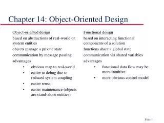
Understanding Design • A process that uses the products of analysis to produce a specification for implementing a system. • A logical description of how a system will work. • Emphasizes a conceptual solution (in software and hardware) that fulfills the requirements, rather than its implementation. • “do the right thing (analysis), and do the thing right (design)”.
Analysis Focus on understanding the problem Idealized design Behavior System structure Functional requirements A small model Design Focus on understanding the solution Operations and Attributes Performance Close to real code Object lifecycles Non-functional requirements A large model Analysis Versus Design
Object Oriented Design • The specification of a logical software solution in terms of software objects, • such as their classes, attributes, methods, and collaborations. • During object-oriented design (or simply, object design) there is an emphasis on defining software objects and how they collaborate to fulfill the requirements.
5.2 Architectural Design • Architectural Patterns • Resolution of Architectural Factors • Identify Design Elements • Organizing the design model packages
What is An Architectural Pattern? • An architectural pattern expresses a fundamental structural organization schema for software systems. It provides a set of predefined subsystems, specifies their responsibilities, and includes rules and guidelines for organizing the relationships between them – Buschman et al, “Pattern-Oriented Software Architecture— A System of Patterns”” • Architectural patterns- Common Architectural Styles • Layers • Model-view-controller (M-V-C) • Pipes and filters • Blackboard
Typical Layering Approach Specific functionality General functionality
Examples of Architectural Patterns - Layers 1) Pattern Name: Layers 2) Context A large system that requires decomposition. 3) Problem A system which must handle issues at different levels of abstraction. For example: hardware control issues, common services issues and domain-specific issues. It would be extremely undesirable to write vertical components that handle issues at all levels. The same issue would have to be handled (possibly inconsistently) multiple times in different components.
Examples of Architectural Patterns - Layers 4) Forces Parts of the system should be replaceable Changes in components should not ripple Similar responsibilities should be grouped together Size of components -- complex components may have to be decomposed 5) Solution Structure the systems into groups of components that form layers on top of each other. Make upper layers use services of the layers below only (never above). Try not to use services other than those of the layer directly below (don’t skip layers unless intermediate layers would only add pass-through components).
Modeling Architectural Layers • Architectural layers can be modeled using stereotyped packages • <<layer>> stereotype
<<layer>>Application <<layer>>Business-Specific <<layer>>Middleware Layer – Reuse driving
Upward Collaboration with Observer • When the lower Application or Domain layer needs to communicate upward with the Presentation layer, it is usually via the Observer pattern • UI objects in the higher Presentation layer implement an interface such as Property Listener or AlarmListener, and are subscribers or listeners to events (such as property or alarm events) coming from objects in the lower layers. • The lower layer objects are directly sending messages to the upper layer UI objects,but the coupling is only to the objects viewed as things that implement an interface such as PropertyListener, not viewed as specific GUI windows.
Comments on typical coupling between layers • All higher layers have dependencies on the Technical Services and Foundations layer • For example, in Java all layers depend onjava.util package elements • It is primarily the Domain layer that has dependency on the Business Infrastructure layer • Presentation layer makes calls on the Application layer, which makes service calls on the Domain layer; • the Presentation layer does not call on the Domain, unless there is no Application layer. • If it is a single-process "desktop" application, software objects in the Domain layer are directly visible to, or passed between, Presentation, Application, and to a lesser extent, Technical Services. • If it is a distributed system, then serializable replicates (also known as data holder or value objects) of objects in the Domain layer are usually passed to a Presentation layer. • In this case, the Domain layer is deployed on a server computer, and client nodes get copies of server data.
Terminology: Tiers, Layers, and Partitions • The original notion of a tier in architecture was a logical layer, not a physical node, but the word has become widely used to mean a physical processing node (or cluster of nodes) • such as the "client tier" (the client computer).. • The layers of an architecture are said to represent the vertical slices • The partitions represent a horizontal division of relatively parallel subsystems of a layer.
Client A Client N …... Server Layer - N-Tier(C/S)
Thinner client, thicker server Client B Client A Client C Application Application WWW Browser CORBA Beans DCOM ADO/R Business Object Services Business Object Engine Web Server HTML CGI ASP Java Beans ETS COM MTS Business Object Server Business Object Services Business Object Services Business Object Engine Business Object Engine Layer - N-Tier(3 tier) Relational Database Server(s)
Layer - N-Tier(n-tier) HTML, Script Languages, ... Client/Browser Web Server JSP, Servlets, CGI, ... Application Server EJB, CORBA, COM+ Database Server Legend System Native languages
Architectural Pattern - MVC • Name: MVC (Model-View-Controller) • Context and forces: we have a data model and several representations of the data – We want to modularize the system – Data representation must be kept up to date • Problem: how to modularize the system • Solution: the model holds the data (and does data modification), the view represents the data, the controller handles user input
Model-View-Controller Architecture Themodel-view-controller architecture (MVC) separates application data (contained in the model) from graphical presentation components (the view) and input-processing logic (the controller). Java’s Swing components implement a variation of MVC that combines the view and controller into a single object, called a delegate. The delegate provides both a graphical presentation of the model and an interface for modifying the model. For example, every JButton has an associated ButtonModel for which the JButton is a delegate.The ButtonModel maintains state information, such as whether the JButton is pressedand whether the JButton is enabled, as well as a list of ActionListeners. The JButton provides a graphical presentation and modifies the ButtonModel’s state.
Examples of Architectural Patterns - Blackboard 1) Pattern Name Blackboard 2) Context A domain in which no closed (algorithmic) approach to solving a problem is known or feasible. Examples are AI systems, voice recognition, and surveillance systems. 3) Problem Multiple problem-solving agents (knowledge agents) must cooperate to solve a problem that cannot be solved by any of the individual agents. The results of the work of the individual agents must be accessible to all the other agents so they can evaluate whether they can contribute to finding a solution and post results of their work.
Examples of Architectural Patterns - Blackboard 4) Forces Sequence in which knowledge agents can contribute to solving the problem is not deterministic and may depend on problem solving strategies. Input from different agents (results or partial solutions) may have different representations. Agents do not know of each other's existence directly but can evaluate each other's posted contributions 5) Solution A number of Knowledge Agents have access to a shared data store called the Blackboard. The blackboard provides an interface to inspect and update its content. The Control module/object activates the agents following some strategy. Upon activation an agent inspects that blackboard to see if it can contribute to solving the problem. If the agent determines that it can contribute, the control object can allow the agents to put its partial (or final) solution on the board.
Resolution of Architectural Factors • Recording Architectural Alternatives, Decisions, and Motivation - technical memos • Example of Technical Memo
Use case <<layer>> <<layer>> <<layer>> <<layer>> General Application General Services System Services Special Application Layered Architecture Use case report Glossary Supplementary Specification Design Model Overview Requirement Model Design Model Use case realization Architecture Mechanism
Technical Memo • All architectural methods recommend keeping a record of alternative solutions, decisions, influential factors, and motivations for the noteworthy issues and decisions. • Such records have been called technical memos, issue cards, and architectural approach documents, with varying degrees of formality and sophistication. • In some methods, these memos are the basis for yet another step of review and refinement. • In the UP, the memos should be recorded in the SAD. • An important aspect of the technical memo is the motivation or rationale. • Explaining the rationale of rejecting the alternatives is important.
Architectural Information in the UP Artifacts • The architectural decisions are recorded in the SAD(Software Architecture Document). • This includes the technical memos and descriptions of the architectural views.
Sample Structure of a SAD • Architectural Representation • (Summary of how the architecture will be described in this document, such as using by technical memos and the architectural views. This is useful for someone unfamiliar with the idea of technical memos or views. Note that not all views are necessary.) • Architectural Factors and Decisions • (Reference to the Supplementary Specification to view the Factor Table. Also, the set of technical memos the summarize the decisions.) • Logical View • (UML package diagrams, and class diagrams of major elements. Commentary on the large scale structure and functionality of major components.) • Process View • (UML class and interaction diagrams illustrating the processes and threads of the system. Group this by threads and processes that interact. Comment on how the interprocess communication works (e.g., by Java RMI). • Use-Case View • (Brief summary of the most architecturally significant use cases. UML interaction diagrams for some architectural significant use-case realizations, or scenarios, with commentary on the diagrams explaining how they illustrate the major architectural elements.) • Deployment View • (UML deployment diagrams showing the nodes and allocation of processes and components. Commentary on the networking.) • Data View • Overview of the persistent data schema, the schema mapping from objects to persistent data (usually in a relational database), the mechanism of mapping from objects to a database, database stored procedures and triggers. • A view onto the UP Data Model, visualized with UML class diagrams used to describe a data model.
Identify Design Elements Purpose:To analyze interactions of analysis classes to identify design model elements • Identify Classes, Active Classes and Subsystems • Identify Subsystem Interfaces • Identify and Specify Events • Identify and Specify Signals
Identify Design Elements analysis classes represent conceptual things which can perform behavior. In design, analysis classes evolve into a number of different kinds of design elements: • classes, to represent a set of rather fine-grained responsibilities; • subsystems, to represent a set of coarse-grained responsibilities, perhaps composed of a further set of subsystems, but ultimately a set of classes; • active classes, to represent threads of control in the system; • interfaces, to represent abstract declarations of responsibilities provided by a class or subsystem.
Identify Design Elements In addition, in design we shall also identify: • events, which are specifications of interesting occurrences in time and space that usually (if they are noteworthy) require some response from the system; and • signals, to represent asynchronous mechanisms used to communicate certain types of events within the system. Events and the Signals that are used to communicate them, allow us to describe the asynchronous triggers of behavior to which the system must respond.
Packages versus Subsystems Subsystems • Provide behavior • Completely encapsulate their contents • Are easily replaced Packages • Don’t provide behavior • Don’t completely encapsulate their contents • May not be easily replaced Client Class Package B ClassB1 <<subsystem>> ClassB2 Subsystem A Encapsulation is the key!
<<Interface>> <<subsystem>> Subsystem K Y() Z() Identifying Subsystems “Superman Class”
<<subsystem>> Billing System IBillingSystem submitBill(forTuition : Double, forStudent : Student) <<boundary>> <<subsystem>> Course Catalog CourseCatalogSystem System //get course offerings() ICourseCatalogSystem getCourseOfferings(forSemester : Semester, forStudent : Student) : CourseOfferingList initialize() Example: Design Subsystems and Interfaces Analysis Design
<<subsystem>> CourseCatalogSystem ICourseCatalogSystem Modeling Convention: Subsystems and Interfaces <<subsystem>> package <<subsystem proxy>> class Interfaces start with an “I” <<subsystem proxy>> CourseCatalogSystem ICourseCatalogSystem getCourseOfferings(forSemester : Semester, forStudent : Student) : CourseOfferingList getCourseOfferings() initialize() initialize()