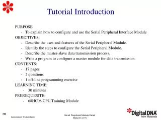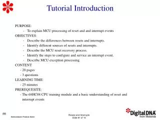
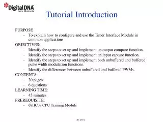
Tutorial Introduction
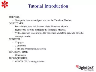
This tutorial provides a comprehensive introduction to configuring and using the Timer Interface Module in common applications using the 68HC08 microcontroller. The objectives include setting up output compare and input capture functions, implementing both unbuffered and buffered pulse width modulation (PWM) functions, and distinguishing between the two PWM types. The content spans 20 pages, includes 6 questions, and is designed for an estimated learning time of 45 minutes. Prior knowledge of the 68HC08 CPU and its Timer Interface Module is recommended.

Tutorial Introduction
E N D
Presentation Transcript
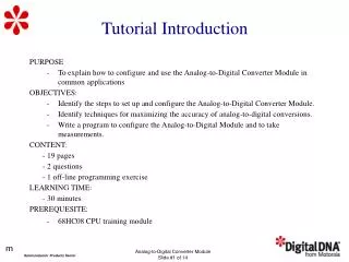
Tutorial Introduction PURPOSE • To explain how to configure and use the Timer Interface Module in common applications OBJECTIVES: • Identify the steps to set up and implement an output compare function. • Identify the steps to set up and implement an input capture function. • Identify the steps to set up and implement both unbuffered and buffered pulse width modulation functions. • Identify the differences between unbuffered and buffered PWMs. CONTENTS: • 20 pages • 6 questions LEARNING TIME: • 45 minutes PREREQUISITE: • 68HC08 CPU Training Module
Timer Interface ModuleBlock Diagram PS2 PS1 PS0 Internal Bus Clock Prescaler TSTOP TRST 16-bit Counter TOF Interrupt Logic 16-bit Comparator TOIE TMOD Port Logic TOV0 TnCH0 ELS0B ELS0A CH0MAX 16-bit Comparator TCH0 CH0F Interrupt Logic Interrupt Logic 16-bit Latch CH0IE CH0IE MS0A MS0B MS0B Port Logic TOV1 TnCH1 ELS1B ELS1A CH1MAX 16-bit Comparator TCH1 CH1F Interrupt Logic Interrupt Logic 16-bit Latch CH1IE CH1IE MS1A PS2 PS1 PS0 Internal Bus Clock Prescaler TSTOP TRST 16-bit Counter TOF Interrupt Logic Timer Reference 16-bit Comparator TOIE TMOD Port Logic TOV0 TnCH0 ELS0B ELS0A CH0MAX Timer Channel 0 16-bit Comparator TCH0 CH0F Interrupt Logic 16-bit Latch CH0IE MS0A MS0B Internal Bus Port Logic TOV1 TnCH1 ELS1B ELS1A CH1MAX Timer Channel 1 16-bit Comparator TCH1 CH1F Interrupt Logic 16-bit Latch CH1IE MS1A
Timer Interface ModuleTime Reference PS2 PS2 PS1 PS1 PS0 PS0 Internal Bus Clock Prescaler Prescaler TSTOP TSTOP TRST TRST 16-bit Counter 16-bit Counter TOF TOF Interrupt Logic Interrupt Logic 16-bit Comparator 16-bit Comparator TOIE TOIE TMOD TMOD
Timer Interface ModuleTime Reference PS2 PS2 PS1 PS1 PS0 PS0 Internal Bus Clock Prescaler Prescaler TSTOP TSTOP TRST TRST 16-bit Counter 16-bit Counter TOF TOF Interrupt Logic Interrupt Logic 16-bit Comparator 16-bit Comparator TOIE TOIE TMOD TMOD
Timer Interface ModuleOutput Compare Overview 16-BIT FREE RUNNING COUNTER 16-BIT COUNTER OCx PIN CONTROL LOGIC = ? 16-BIT COMPARE 16-BIT COMPARE Clear (05 & 08) Set (05 & 08) Toggle (08 Only) 16-BIT OUTPUT COMPARE LATCH Status Flag Interrupt Enable Request Interrupt
Timer Interface ModuleOutput Compare Overview 16-BIT FREE RUNNING COUNTER 16-BIT COUNTER OCx PIN CONTROL LOGIC = ? 16-BIT COMPARE 16-BIT COMPARE Clear (05 & 08) Set (05 & 08) Toggle (08 Only) 16-BIT OUTPUT COMPARE LATCH Status Flag Interrupt Enable Request Interrupt
Timer Interface ModuleOutput Compare Applications • Perform a simple timed event • Perform a periodic interrupt event • Implement a single pulse with variable width • Generate a pulse width modulated signal
Timer Interface ModuleOutput Compare Function 0:0 General Purpose I/O ELS0B ELS0A 0:1 Toggle Output on Compare 1:0 Clear Output on Compare 1:1 Set Output on Compare PS2 PS1 PS0 Internal Bus Clock Prescaler TSTOP TRST 16-bit Counter 16-bit Counter TOF Interrupt Logic 16-bit Comparator TOIE TMOD Port Logic TOV0 TnCH0 TnCH0 ELS0B ELS0A CH0MAX 16-bit Comparator TCH0 TCH0 CH0F Interrupt Logic 16-bit Latch CH0IE MS0A 1 MS0B 0 Internal Bus Port Logic TOV1 TnCH1 ELS1B ELS1A CH1MAX 16-bit Comparator TCH1 CH1F Interrupt Logic 16-bit Latch CH1IE MS1A
Timer Interface ModuleInput Capture Overview 16-BIT FREE-RUNNING COUNTER ICx EDGE SELECT & DETECT Latch 16-BIT INPUT CAPTURE LATCH Status Flag Interrupt Enable Request Interrupt Rising Edges (05 & 08) Falling Edges (05 & 08) Any Edge (08 Only)
Timer Interface ModuleInput Capture Applications • Perform time reference to an external event • Measure an input period • Measure the width of an input pulse • Provide additional external interrupts
Timer Interface ModuleInput Capture Function 0:0 General Purpose I/O ELS1B ELS1A 0:1 Capture on Rising Edge 1:0 Capture on Falling Edge 1:1 Capture on Either Edge PS2 PS1 PS0 Internal Bus Clock Prescaler TSTOP TRST 16-bit Counter 16-bit Counter TOF Interrupt Logic 16-bit Comparator TOIE TMOD Port Logic TOV0 TnCH0 ELS0B ELS0A CH0MAX 16-bit Comparator TCH0 CH0F Interrupt Logic 16-bit Latch CH0IE MS0A MS0B 0 Internal Bus Port Logic TOV1 TnCH1 TnCH1 ELS1B ELS1A CH1MAX 16-bit Comparator TCH1 TCH1 CH1F Interrupt Logic 16-bit Latch CH1IE MS1A 0
Timer Interface ModulePulseWidth Modulation Overview Period Duty Cycle Period 25% Duty Cycle PWM Duty Cycle 50% Duty Cycle PWM
Timer Interface ModuleUnbuffered Pulse Width Modulation 0:0 General Purpose I/O ELS0B ELS0A 0:1 Toggle Output on Compare 1:0 Clear Output on Compare 1:1 Set Output on Compare 1 0 TCH0 Duty Cycle = TMOD ELS0B ELS0A 1 1 Overflow Compare PS2 PS1 PS0 Internal Bus Clock Prescaler TSTOP TRST 16-bit Counter 16-bit Counter TOF Interrupt Logic 16-bit Comparator 16-bit Comparator TOIE Toggle on Overflow TMOD TMOD Port Logic 1 TOV0 TnCH0 TnCH0 ELS0B ELS0A CH0MAX 16-bit Comparator TCH0 TCH0 CH0F Interrupt Logic 16-bit Latch CH0IE MS0A 1 0 MS0B Internal Bus Port Logic TMOD Period TOV1 TMOD ³ TCH0 TnCH1 ELS1B ELS1A CH1MAX 16-bit Comparator TCH1 CH1F Interrupt Logic Pulse Width 16-bit Latch TCH0 CH1IE MS1A
Timer Interface ModuleUnbuffered Pulse Width Modulation 0:0 General Purpose I/O ELS0B ELS0A 0:1 Toggle Output on Compare 1:0 Clear Output on Compare 1:1 Set Output on Compare 1 0 TCH0 Duty Cycle = TMOD ELS0B ELS0A 1 1 Overflow Compare PS2 PS1 PS0 Internal Bus Clock Prescaler TSTOP TRST 16-bit Counter 16-bit Counter TOF Interrupt Logic 16-bit Comparator 16-bit Comparator TOIE Toggle on Overflow TMOD TMOD Port Logic 1 TOV0 TnCH0 TnCH0 ELS0B ELS0A CH0MAX 16-bit Comparator TCH0 TCH0 CH0F Interrupt Logic 16-bit Latch CH0IE MS0A 1 0 MS0B Internal Bus Port Logic TMOD Period TOV1 TMOD ³ TCH0 TnCH1 ELS1B ELS1A CH1MAX 16-bit Comparator TCH1 CH1F Interrupt Logic Pulse Width 16-bit Latch TCH0 CH1IE MS1A
Timer Interface ModuleUnbuffered Pulse Width Modulation Compare Interrupt Overflow Interrupt Overflow Interrupt Overflow Interrupt New TCH Value New TCH Value New TCH Value Compare Interrupt Compare Interrupt Compare Interrupt Compare Interrupt New TCH Value New TCH Value Intermediate TCH Value Period Too Late! Too Late! Compare Interrupt Period TCH < TCNT
Timer Interface ModuleUnbuffered Pulse Width Modulation Overflow Interrupt New TCH Value Overflow Interrupt Overflow Interrupt Compare Interrupt New TCH Value Compare Interrupt Compare Interrupt New TCH Value Compare Interrupt Compare Interrupt New TCH Value Intermediate TCH Value New TCH Value Period Too Late! Too Late! Compare Interrupt Period TCH < TCNT
Timer Interface ModuleUnbuffered Pulse Width Modulation Overflow Interrupt New TCH Value Overflow Interrupt Overflow Interrupt Compare Interrupt New TCH Value Compare Interrupt Compare Interrupt New TCH Value Compare Interrupt Compare Interrupt New TCH Value Intermediate TCH Value New TCH Value Period Too Late! Too Late! Compare Interrupt Period TCH < TCNT
Timer Interface ModuleBuffered Pulse Width Modulation 0:0 General Purpose I/O ELS0B ELS0A 0:1 Toggle Output on Compare 1:0 Clear Output on Compare 1:1 Set Output on Compare X X X PS2 PS1 PS0 Internal Bus Clock Prescaler TSTOP TRST 16-bit Counter 16-bit Counter TOF Interrupt Logic 16-bit Comparator 16-bit Comparator TOIE Toggle on Overflow TMOD TMOD Period Port Logic TOV0 1 TnCH0 TnCH0 ELS0B ELS0A CH0MAX 16-bit Comparator TCH0 TCH0 CH0F Interrupt Logic 16-bit Latch CH0IE MS0A X MS0B 1 Internal Bus Port Logic TOV1 TnCH1 ELS1B ELS1A CH1MAX 16-bit Comparator TCH1 TCH1 CH1F Interrupt Logic 16-bit Latch CH1IE MS1A
Timer Interface ModuleBuffered Pulse Width Modulation 0:0 General Purpose I/O ELS0B ELS0A 0:1 Toggle Output on Compare 1:0 Clear Output on Compare 1:1 Set Output on Compare X X X PS2 PS1 PS0 Internal Bus Clock Prescaler TSTOP TRST 16-bit Counter 16-bit Counter TOF Interrupt Logic 16-bit Comparator 16-bit Comparator TOIE Toggle on Overflow TMOD TMOD Period Port Logic TOV0 1 TnCH0 TnCH0 ELS0B ELS0A CH0MAX 16-bit Comparator TCH0 TCH0 CH0F Interrupt Logic 16-bit Latch CH0IE MS0A X MS0B 1 Internal Bus Port Logic TOV1 TnCH1 ELS1B ELS1A CH1MAX 16-bit Comparator TCH1 TCH1 CH1F Interrupt Logic 16-bit Latch CH1IE MS1A
Question What happens when the value in the output compare register is equal to the value in the 16-bit time reference counter? Click on the BEST choice. a) The output compare flag is set. b) An output compare interrupt is generated if enabled. c) The output pin is set, cleared, or toggled if enabled. d) The output pin is toggled if the toggle on overflow option is enabled. e) a, b, and c f) All of the above
Question What is the fastest frequency that can be achieved for a 6-bit PWM when using a 68HC08 with an 8 MHz bus frequency? Click on your choice. a) 500 kHz b) 250 kHz c) 125 kHz d) 62.5 kHz e) 31.25 kHz
Question Does the 16-bit timer reference counter count up or count down? Click on your choice. a) Count up b) Count down c) Programmable up or down
Question What type of input signal event(s) can the timer be programmed to detect before a valid input capture? Click on your choice. a) Rising Edge only b) Falling Edge only c) Rising and/or Falling Edge
Question Is the output compare interrupt option recommended to change the duty cycle in unbuffered PWMs? Click on your choice. a) Yes b) No c) Does not matter
Question Is the counter overflow interrupt option recommended to change the duty cycle in buffered PWMs? Click on your choice. a)Yes b) No c) Does not matter
Tutorial Completion • TIM Configuration • Output Compare • Input Capture • Unbuffered PWM • Buffered PWM