Download
1 / 18
200 likes | 348 Vues
DESIGNING WITH HIGH-STRENGTH LOW-TOUGHNESS MATERIAL. High strength materials are being increasingly used in designing critical components to save weight or meet difficult service conditions.

E N D
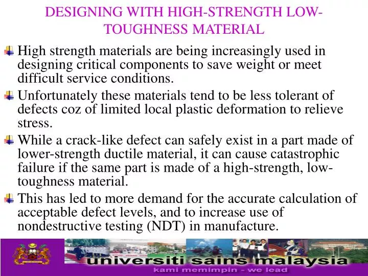
DESIGNING WITH HIGH-STRENGTH LOW-TOUGHNESS MATERIAL • High strength materials are being increasingly used in designing critical components to save weight or meet difficult service conditions. • Unfortunately these materials tend to be less tolerant of defects coz of limited local plastic deformation to relieve stress. • While a crack-like defect can safely exist in a part made of lower-strength ductile material, it can cause catastrophic failure if the same part is made of a high-strength, low-toughness material. • This has led to more demand for the accurate calculation of acceptable defect levels, and to increase use of nondestructive testing (NDT) in manufacture.
DESIGNING WITH HIGH-STRENGTH LOW-TOUGHNESS MATERIAL • Defects can be the result of • Initial flaws in the material, e.g inclusion & cavities • Introduced by production method, e.g welding. • Service conditions, e.g fatigue cracks, stress corrosion cracks.
DESIGNING WITH HIGH-STRENGTH LOW-TOUGHNESS MATERIAL • Fail-safe design • Require a structure to be sufficiently damage to allow defect be detected before they develop to a dangerous size. • Inspection has to be conducted before the structure is put into service to ensure that none of the defects exceeds the critical size. • Structure has to be inspected periodically during its service life to ensure that none of the defects grows to a dangerous size.
DESIGNING WITH HIGH-STRENGTH LOW-TOUGHNESS MATERIAL • The figure shows that it is not strictly necessary to select a material with low crack propagation rate. • In principle the structure can be made to fail safe when cracks propagate fast if the inspection interval is short enough. • However, short inspection periods are not always possible or cost effective. • A better alternative is to use a more sensitive inspection method to reduce the minimum detectable defect size.
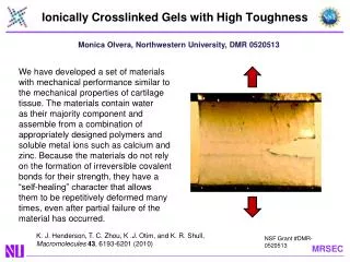
DESIGNING WITH HIGH-STRENGTH LOW-TOUGHNESS MATERIAL • Guidelines for design • Interaction between fracture toughness, allowable crack size & design stress need to be considered. • Toughness – A qualitative measure of the energy require to cause fracture of material. • A material that resist failure by impact is said to be tough • Fracture toughness • The ability of materials containing flaws to withstand load. • Measured using : • Impact testing apparatus – Charpy and Izod test • Another is the area under the true stress-strain curve.
The impact test (a) the Charpy & Izod test (b) dimensions of typical specimens
DESIGNING WITH HIGH-STRENGTH LOW-TOUGHNESS MATERIAL • Designing with ductile unflawed parts, as the load increase the nominal stress increase until it reaches the yield stress and plastic deformation occurs. • In the case of high-strength, low toughness material, as the design stress increases (or as the size of the flaw increase) the stress concentration at edge of crack, the stress intensity KI, increase until reaches KIC and fracture occurs. • Thus the value of KI in a structure design should always be kept below the value of KIC in the same manner that the nominal stress is kept below the yield strength.
DESIGNING WITH HIGH-STRENGTH LOW-TOUGHNESS MATERIAL • The plane-strain conditions at thickness, t, occurs related to the fracture toughness, KIC, and yield strength of the material, YS, according to the relationship : • Condition of failure under plane-strain conditions, where a crack of length 2a exists in a thick, infinitely large plate, KIC = property of material/Fracture toughness, = design parameter, controlled by applied load & shape, a = ½ crack length, controlled by manufacturing method & NDT, Y is a dimensionless shape factor, a function of crack geometry.
DESIGNING WITH HIGH-STRENGTH LOW-TOUGHNESS MATERIAL • Equation must be used in several ways to design against failure. • For example, selecting a material to resist other service requirements automatically fixes KIC. • In addition, if the minimum crack size that can be detectable by the available NDT methods is known equation 2.2 is used to calculate the allowable design stress. • Which must be less then • Alternatively, if the space, weight and operating stress have a limitation, the max allowable crack size can be calculated to check whether it can be detected using routine inspection methods
Define function & service conditions Preliminary construction 1.Preliminary stress analysis 2. Preliminary material selection Working stress Flow chart giving the steps which can be followed in designing fracture-resistant structures. KIC Determine critical crack size Can the critical crack size be achieved by manufacture and can it be detected by available NDT No Yes Are existing subcritical cracks likely to grow ? Yes Determine crack growth rate No Set Q.C and inspection limits
Example – Design of pressure vessel. • Internal pressure, P = 35 MN/m2 • Internal diameter, D = 800 mm • Manufactured by welding of sheets & welded joints inspected by NDT, capable of detecting surface cracks > 15 mm. • Consider use AISI 4340, tempered at 260°C, Yield strength = 1640 MPa & KIC = 50 MPa m1/2. Treat as thin-walled cylinder, wall thickness, t ; t = PD / 2w where w = working stress. • n = 2, working stress = 820 MPa & wall thickness is calculated as t = 17.1 mm.
Example Pressure vessel thin-walled cylinder with thickness t
Critical crack size calculated from, KIC = [1.1/Q] πa • Taking conservative case of semicircular crack, a/2C = 0.5, value of Q can be estimated from Table for /YS = 0.5 as Q = 2.35. • Critical crack length, a = 2.3 mm. Too small to detect. • Use same steel but tempering at 425°C gives yield strength = 1420 MPa & KIC = 87.4 MPa m1/2. Follow same procedure gives t = 19.7 & a = 18.74 mm. Can be detected by NDT & suitable monitoring technique can be arranged. • Steel 4340 tempered at this condition is suitable for making the pressure vessel. • Other factors like availability of material, weldability, weight of vessel and cost have to be taken into consideration before this steel is finally selected
DESIGNING WITH HIGH-STRENGTH LOW-TOUGHNESS MATERIAL • Leak-before-burst • Based on concept of if vessel containing pressurized gas/liquid contains growing crack, toughness should be sufficiently high to tolerate a defect size which will allow the contents to leak out before failure occurs. • For leakage, crack must grow through wall thickness, t. Design stress – assumed that failure is due to tensile stresses occurring tangentially in the walls. • Should take into account the material, operating environment, & P constant or varying in cyclic fashion.