Download

1 / 17
170 likes | 292 Vues
A. Brooks identifies critical time points that create unstable force distribution on TF coils, particularly under high MC currents and low TF coil currents. This paper discusses the required radial preload to maintain structural integrity, detailing design iterations on TF coil preload systems since 2/23/05. Key findings indicate that a 4000 lb preload produces "stuck" coils when the friction coefficient exceeds 0.1. The design also incorporates jack screw devices and Bellville washers to ensure consistent force application, addressing potential deflections and stresses under operating conditions.

E N D
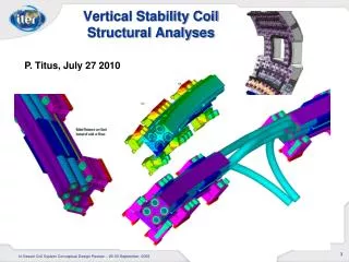
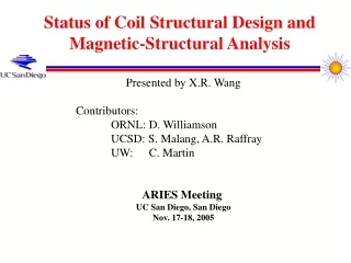
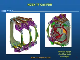
TF Coil Radial PreloadRequired for Structural Stability • A. Brooks has identified some time points in the reference current scenarios which produce an unstable force distribution on the TF coils (positive net radial force and torque about major radius). • This occurs when MC currents are high and the TF coil current is relatively low. TF Coil Preload Design Iteration 2/23/05
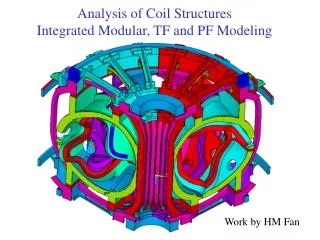
Comparison of Deformations fromSlipped and Stuck TF Coils Zero Radial Preload Allows Coils to Slip at Interface (old 2x6 WP) Radial Preload Sufficient to “Stick” Coils at Interface (new 3x4 WP) TF Coil Preload Design Iteration 2/23/05
Wedge-to-Wedge Friction Coefficient ()as a Function of Radial Preload • A 4000 lb preload will produce a “stuck” coil set if >0.1. • This is a factor of 2 below the 0.2 value which is expected to be easily achieved. TF Coil Preload Design Iteration 2/23/05
SS WedgeCastings Radial Preload Applied to Back Leg • Radial pre-load required to ensure wedging Back SS Strap Radial Pre-load Wedging TF Coil Preload Design Iteration 2/23/05
Breakout of Reaction Structures, Radial Preload • 4,000 LBF per pusher provides twice the required pre-load to prevent any movement as TF Fields ramp up or down • Radial preload applied with jack screw device top and bottom. • Bellville washers in parallel provide relatively constant force over required thermal excursions TF Coil Preload Design Iteration 2/23/05
Breakout of Reaction Structures, Wedging Locking Pins add redundancy to wedging design Wedging fixes location while shim bags lock coil in case with respect to supports Wedging Extends 50 degrees around the upper and lower TF Castings extend as High as the Upper TF Support Castings TF Coil Preload Design Iteration 2/23/05
Centering Forces for TF Only • Centering forces concentrate on inner leg • Moving preload to inner leg removes unnecessary stress TF Coil Preload Design Iteration 2/23/05
Jack Screw Device Added Pulls Coil Forward • Use available space for preload jacking screws instead of pins Bellville washers ensure constant 4000 lbf load TF Coil Preload Design Iteration 2/23/05
Jack Screw Device Added Pulls Coil Forward TF Coil Preload Design Iteration 2/23/05
Top Down View, Center Stack • Nuts accessible for maintenance from top of vessel TF Coil Preload Design Iteration 2/23/05
Access Holes In Top Hat Structure • Removal of PF4 allows for access to bracket hardware TF Coil Preload Design Iteration 2/23/05
Jack Screw Device Added Pulls Coil Forward TF Coil Preload Design Iteration 2/23/05
TF Coil Bonded to Casting With Front Preload • Model updated to reflect preload application at front of coil directly to wedge castings TF Coil Preload Design Iteration 2/23/05
Deflections With Front Preload and Cool Down • Preload contributes little or no deflection before application of operating load TF Coil Preload Design Iteration 2/23/05
Stresses Due to Preload + .5Tesla TF Only Operation • Compares to 195 MPa for unbonded back leg preload run • Bonded Bending Stress at 127 MPa • Early results show about 177 MPa for unbonded front preload TF Coil Preload Design Iteration 2/23/05
New TF Flag Design TF Coil Preload Design Iteration 2/23/05
Breakout of Reaction Structures, Vertical Support • Lower Support reacts gravity load and fixes vertical position. • Allows for Outward radial motion • Upper Support allows for application of upward or downward load. • Allows for Outward radial motion TF Coil Preload Design Iteration 2/23/05