Download
1 / 23
360 likes | 992 Vues
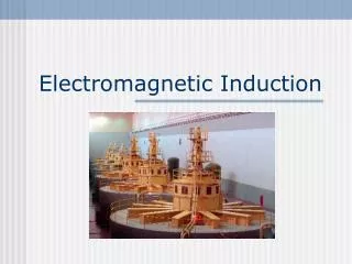
Induced e.m.f. (electromotive force) and the Transformer. Introduction. Remember that a current travelling through a coil can produce a magnetic field (solenoid!!). Question: Can a magnetic field produce an electric current? The answer is YES!

E N D
Introduction • Remember that a current travelling through a coil can produce a magnetic field (solenoid!!). • Question: • Can a magnetic field produce an electric current? • The answer is YES! • A magnetic field can cause an electric current (it’s called magnetic induction), BUT the magnetic field must be changing.
Magnetic Flux Magnetic flux, represented by the Greek letter Φ (phi), is a measure of quantity of magnetism, taking into account the strength and the extent of a magnetic field. The SI unit of magnetic flux is the weber It is in the discussion of objects like transformers and solenoids.
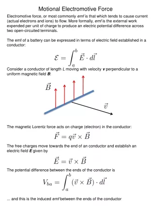
Induced e.m.f. When a conductor is moved so that it interacts with a magnetic field, an e.m.f (electromotive force) is induced in the conductor. If the conductor is in a closed loop, an induced current flows. The conductor must be placed at an angle to the magnetic field. There is 0 e.m.f. if the coil is parallel to the field.
The Induced e.m.f. The magnitude of the induced e.m.f. is dependent on the motion of the moving magnet. The direction of the induced e.m.f. is dependent on the direction of motion of the conductor and the magnetic field.
The Magnitude of the e.m.f. • The magnitude of the e.m.f. is determined from Faraday’s law. • Faraday’s law states that: The magnitude of the induced e.m.f. is directly proportional to the rate of change of magnetic flux.
The Magnitude of the e.m.f. • Therefore, the e.m.f. can be increased by: • Increasing the speed of the magnet and conductor • The strength or intensity of the magnetic field. • The area the conductor takes up. • The number of turns on the coil, if one is used.
The Direction of the e.m.f. Fleming’s Right hand rule is used to predict the direction of the induced e.m.f. (current) if a wire cuts a magnetic field. First finger – Field thuMb – Motion seCond finger – induced Current
The A.C. Generator • This is a machine that is used to convert kinetic (mechanical) energy into electrical energy. • It generates an alternating current. • Again here, a coil is located within a C-shaped magnet, which is connected to slip rings and brushes. • Coils are rotated within a magnetic field and this induces an e.m.f.
The A.C. Generator • How it works? • By using Fleming's right hand rule: We see that there is an induced current in the coils. • The slip rings don’t have a gap (unlike commutators) and these carry the induced e.m.f. • The e.m.f is alternating because of the slip rings. • Maximum V (+/-) occurs when the coil is vertical. A.C. Output
The Transformer • This is a device used to change the voltage of an alternating supply without changing the frequency. • A transformer is made up 2 coils of insulated copper wound on a soft iron core. • The core is made up of “laminates” of the iron which are electrically, but not magnetically, insulated from each other.
Why Transformers? • Transformers are mainly used to transfer electrical energy using a.c. • When transferring the energy, the transformer can change the voltage to a larger or smaller value. • By transmitting in high voltages less electrical energy is wasted. • Transformers are mainly used to change high voltages, transmitted across large distances, into lower, safe voltages for everyday applications
THE TRANSFORMER How it works: The transformer is based on electromagnetic induction. When an alternating voltage is applied to the primary coil, the resulting a.c. produces a changing magnetic field in the core (solenoid). The changing magnetic field induces an e.m.f. in the secondary coil. Remember nothing is conducted across the core.
The Transformer • The magnitude of the induced e.m.f is dependent on : • The alternating voltage applied in the primary coil and • The number of turns in the primary, Np, and secondary coils, Ns.
Features of a Transformer • It has an efficiency usually better than 99%. • Efficiency = output power × 100% input power • The high efficiency is due to the fact that nothing moves in a transformer, i.e. no friction. NB: Power = IV
Types of transformers • There is the step-up and step-down transormer. • In the step-up, there is more turns in the secondary coil, Ns > Np. This means that the output voltage, Vs, is > the input voltage, Vp. • In the step-down, Ns < Np. Also, Vs < Vp.
The Ideal Transformer • For an ideal transformer: • Input power = output power • Pout = Pin • Input is in the primary coil, output is in the secondary coil. • Therefore: Ps = Pp • i.e. IsVs = IpVp • Rearranging we get:
The Ideal transformer • It is also seen that: • where Ns / Np is called the turns- ratio. • If all of the ratio above is > 1 it is a step-up transformer. • If all of the ratio above is < 1 it is a step-down transformer.