Download
1 / 26
380 likes | 1.11k Vues
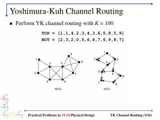
Channel Flow Routing. Steady vs. Unsteady Flow. Steady Unsteady. Unsteady flow through channels and reservoirs. Affect of channel or reservoir storage on flow hydrographs Reduce peak flows Prolong hydrograph base times. ?. A. B. Routing Example. Affected by Slope Shape Roughness

E N D
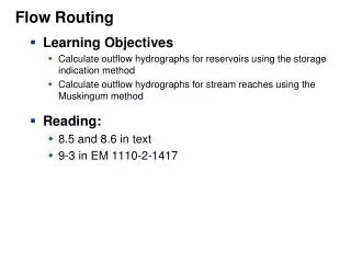
Steady vs. Unsteady Flow • Steady • Unsteady
Unsteady flow through channels and reservoirs • Affect of channel or reservoir storage on flow hydrographs • Reduce peak flows • Prolong hydrograph base times
? A B Routing Example • Affected by • Slope • Shape • Roughness • Storage
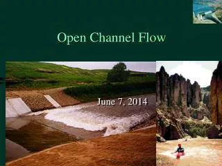
Flow Routing Channel reach or Reservoir Inflow Hydrograph Outflow Hydrograph
Flow Routing Used To: • Determine impacts of • Channel modifications • Reservoir spillway modifications • Design structures to • Control storm water • Mitigate flood flows • Trap sediment
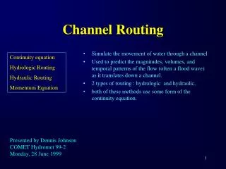
Storage Routing Methods • Based on the continuity equation • Also known as hydrologic routing • Methods include: • Basic storage routing • Muskingum routing • Convex Routing • Kinematic Routing
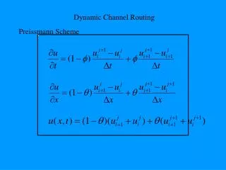
Hydraulic Flow Routing • Based on momentum and continuity equations • Usually done by a numerical solution of the governing equations or by the method of characteristics.
q(x,t) v Area = A dx Continuity and Momentum Equations: A Review I = O + DS
Continuity Equation Volume of the control element Inflow Outflow Continuity equation
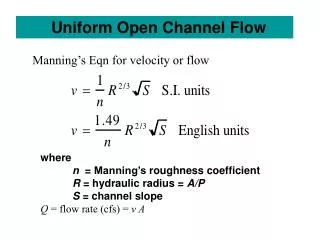
Storage Routing • Storage based on: • Channel geometry • Depth of flow • Flow rate • can be related to depth of flow through Manning’s equation assuming steady, uniform flow • Storage can be based on the average cross-sectional area of the reach for a given flow rate
Storage • Storage can be based on the average cross-sectional area of the reach for a given flow rate. • Length of the channel section multiplied by the average cross-sectional area of the channel at a given flow rate would give the storage in the reach at that flow rate.
Other inflows (or outflows) • Tributary inflows • Overland flows • Ground water contributions
Channel routing • Channel usually divided into several reaches where outflow from one become inflow to the next. • Reaches should have fairly uniform hydraulic properties. • Routing interval should not exceed 1/5 to 1/3 of the time to peak of the hydrograph being routed. • Routing interval should not exceed travel time through the reach. • Common method to solve is to plot characteristic curves (S+ODt/2 and S-ODt/2 versus discharge or depth.
Example • A channel is 2500 ft long, has a slope of 0.09% and is clean with straight banks and no rifts or deep pools. The appropriate Manning’s n is 0.030. A typical cross section is shown in the figure on the next page. Along the length of the channel there is no lateral inflow. The inflow hydrograph to the reach is triangular in shape with a base time of 3 hr, a time to peak of 1 hour and a peak flow rate of 360 cfs. Route the hydrograph through the channel reach using the storage routing procedure.
S y2 Muskingum Method Storage Routing Muskingum Routing
Muskingum Routing • Storage in reach is a linear function of both the inflow and outflow rate. • x and k must be determined from channel characteristics (For best results based on observed hydrographs). • x of zero corresponds to reservoir storage routing; x of ½ makes the storage a function of the average flow rate in the reach.
Muskingum Routing (no streamflow records) • In the absence of streamflow records, k may be estimated as the flow travel time in the reach and x may be taken as about 0.25.
Muskingum-Cunge Method • Procedure to get better estimates for k and x. • c represents a flood wave celerity • m comes from the uniform flow equation and may be taken as 5/3. • v is the velocity at bankful discharge
Muskingum-Cunge • qo is the flow per unit width generally calculated at the peak flow rate. • So is the slope of the channel.
Example: Muskingum-Cunge Method • Repeat storage routing example using the Muskingum-Cunge method.
Convex Routing • Involves only inflow-outflow hydrograph relationships i.e. continuity equation is not directly involved. • C is a parameter between 0 and 1.0 and can be estimated from:
Convex Routing • Travel time is calculated by Dt=CK where K can be approximated by the travel time through the reach. • May result in an inconvenient time interval. • The C value of C* for a more convenient time interval can be calculated from where Dt is from the equation above and the ratio of Dt*/Dt is kept close to unity.
Example: Convex Routing Repeat the previous example problem using Convex Routing.