Download
1 / 55
580 likes | 847 Vues
#3] Giant Magnetoresistance: Experimentally Driven 1986-1989; Theoretically Modeled 1989; IT Applications into 1990’s First Commerical Hard-Disks with GMR Sensors (IBM) 1998. Effect parallel / antiparallel thin magnetic films separated by non-magnetic spacer

E N D
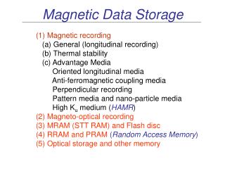
#3] Giant Magnetoresistance: Experimentally Driven 1986-1989; Theoretically Modeled 1989; IT Applications into 1990’sFirst Commerical Hard-Disks with GMR Sensors (IBM) 1998 • Effect parallel / antiparallel thin magnetic films separated by non-magnetic spacer • Nobel Prize in Physics 2007: ‘‘Discovery of GMR’’ • Basic physics involved • Divice applications – computers hard disks • Beyond the GMR • Film from Juelich
1988: … simultaneously, but independent … “Does the electrical resistance depend on the magnetization alignment?” Albert Fert Peter Grünberg
Epitaxial Growth of Multilayers (Idealized) Modern layer-by-layer fabrication techniques: Molecular Beam Epitaxial (MBE) and/or Pulsed Laser Deposition (PLD) Topical use in “interface superconductivity”: LaAlO3 / SrTiO3 -- complex oxides. 2DEG 2D-SC (overfew nm) at TC = 0.2K
Two possible geometries film fabrication Small thicknesses Small diameter
Original Magnetoresistance Measurements Gruenberg et al. Fert et al.
Density of States for Unpolarized and Polarized 3d Metal M = 0 M = (n↑ - n↓) ≠ 0 Paramagnet Ferromagnet
Two Ferromagnets with a Nonmagnetic Spacer in between SPACER SPACER AF aligned F aligned Send current through device. Which has smallest resistance, AF or F??
Parallel Resistor Model with Current of Up/Down Electrons AF ΔR ≈ 50% or less F
Half-Metallic Ferromagnetic, e.g., Hauslers & Skutterudites Spin polarized conduction electrons at Fermi surface (EF) – here 100% ↓- conduction electrons
Multilayer with Two Half-Metallic Ferromagnets Spacer Spacer AF F Spintronics: electronics based upon the spin degrees of freedom, i.e., electron transport controlled / manipulated by spins.
Spin-Dependent Scattering Theory of GRM Camley and Barnas PRL(1989) and Maekawa et al.JPSJ(1991) • C & B: Boltzmann eq. approach with spin dependent coefficient for specular reflection, transmission and anisotropy diffuse scatterings (interface roughness) at the Fe/Cr boundary. N = D/ D . • M et al.: Spin dependent random exchange potential at interfaces (F/NM) and performing a Born approximation: • 1/τ = matrix elements of V(r) • Boltzmann eq. to calculate differences between F and AF coupling between adjacent layers. (ρ↑↓ - ρ↑↑) /ρ↑↑
Now place an insulator between the two magnetic metals Oxide tunnel junction: New physics involve: Quantum mechanical tunneling of electrons. Magnetic fields dependence of tunneling processes.
Theory of TMR “Old” Jullier PL (1975), Mathon & Umerski PRB (1999) • Conductance ratios: RTRM = [(0)-1 -(Hs)-1] / (Hs)-1 40% at Rm.T • Electron tunneling from ferromagnet are spin polarized • Spin polarized tunneling: P = [D(EF) – D (EF)] / [D(E F)+ D(EF)] via net difference of up/down density of states at EF. • Julliere formula: RTMR = (2PLPR ) / [1 – PLPR]at Left and Right electrodes • Different if one has a nonmagnetic metallic interlayer between one of the ferromagnetic electrodes and the insulator. • Due to quantum well states in the metallic interlayer that do not participate in the transport. Only in spin down channel causing an spin asymmetry of tunnel electrons.
IN RESERVE to Juelich CARTOONS Film from Jülich at time of Noble Prize ?
Magnetic interlayer exchange coupling (IEC) … antiparallel … “antiferromagnetic coupling” … at 90º… “biquadratic or 90º-coupling” Consider two ferromagnetic layers separated by a thin spacer layer: Ferromagnet / Non-Ferromagnet / Ferromagnet The ferromagnetic layers interact across the spacer and align … … parallel … “ferromagnetic coupling”
Oscillatory interlayer exchange coupling [1] S.S.P. Parkin, Phys. Rev. Lett. 67, 3958 (1991) [2] D.T. Pierce et al., Phys. Rev. B 49, 14564 (1994) 2) Wedge-shaped Cr spacer Cr spacer thickness D (ML) • only occurs for thin spacers with a thickness of a few nm • is observed for many metallic spacer layers (see [1] for a “periodic table of interlayer coupling”) • oscillates as a function of the spacer thickness D Scanning electron microscopy with spin analysis (SEMPA) [2]: 3) Domain picture of Fe layer grown on Cr wedge 1) Domain picture of Fe single crystal (whisker) with two domains
Origin of oscillatory interlayer exchange coupling Spin-dependent interface reflection gives rise to spin-dependent quantum-well states (QWS). They only form for parallel alignment of the FM layers, but not for antiparallel alignment! Parallel alignment: Antiparallel alignment:
Quantum Well States The energy related to k is quantized. Energy levels shift when the spacer thickness D is varied. A new level crosses EF when D is changed by after M. Stiles (Similar to an electron in a box, where E decreases with increasing D)
What is the origin of spin-dependent reflectivity? P. Lang et al., Phys. Rev. B 53, 9092 (1996) Spin-dependent reflectivity arises from the “potential landscape” seen by the electrons due to the layered structure. Example Co / Cu / Co: Similar band structure for majority electrons and shifted band structure for minority electrons:
Giant magnetoresistance (GMR) Electrical resistance: RP <(>) RAP Ferromagnet Metal Ferromagnet The electrical resistance depends on the relative magnetic alignment of the ferromagnetic layers 19% for trilayers @RT 80% for multilayers @ RT GMR is much larger than the anisotropic magnetoresistance (AMR)
First observations of GMR [1] G. Binasch, P. Grünberg et al., Phys. Rev B 39, 4828 (1989) [2] M.N. Baibich, A. Fert et al., Phys. Rev. Lett. 61, 2472 (1988) Both experiments employ antiferromagnetic interlayer coupling to achieve the antiparallel alignment P. Grünberg, FZJ [1] A. Fert, Paris-Sud [2] GMR AMR
GMR of a spin-valve B. Dieny, J. Magn. Magn. Mater. 136, 335 (1994) Spin-valves make use of the exchange bias effect at the AFM/FM interface 6 nm Ni80Fe20 2.2 nm Cu 4 nm Ni80Fe20 7 nm FeMn CIP-geometry Ferromagnet Anti- Ferromagnet The steep slope at zero field makes spin-valves sensitive field sensors.
Microscopic picture of GMR: Spin-dependent scattering 1) Spin-dependent scattering: rmin rmaj 2) Mott’s two current model: independent current channels for spin-up and spin-down (no spin-flip scattering)
Microscopic picture of GMR: Scattering spin asymmetry The origin of the spin-dependent scattering lies in the spin-split band structure and density of states of 3d transition metals: minority resistance rmin majority resistance rmaj For Co/Cu: rmin>rmaj
Application of GMR: Magnetic field sensor [1] K.M.H. Lenssen et al., J. Appl. Phys. 85, 5531 (1999) Example of a real layer structure [1]: NAF = natural antiferromagnet, SAF = synthetic antiferromagnet
Application of GMR: Read heads in hard disk drives • IBM-HGST Microdrive: • 1 inch diameter • 3600 rpm • 119 Gbit/in2 (Bit size:180 x 30 nm2) • 8 Gbyte in 2006 (340 Mbyte in 1999) Anti-Ferromagnet fixed Ferromagnet free Ferromagnet Disk rotation Current
Application of GMR in hard-disks Advantages of GMR-based read heads compared to AMR or inductive read heads: Stronger MR signal Better signal-to-noise Smaller bits can be read GMR is an interface effect (AMR is a bulk effect): Thinner MR elements Less demagnetization Less wide MR elements Higher sensitivity AMR GMR
What’s beyond GMR? Apply Newton’s third law “Actio = Reactio”: The electric current flow controls the magnetization state Negative current parallel alignment Positive current Antiparallel alignment • Current-induced magnetization switching by spin-transfer torque J.C. Slonczewski, J. Magn. Magn. Mater. 159, L1 (1996); L. Berger, Phys. Rev B 54, 9353 (1996)
Advanced switching concept for spintronic devices Spintronic devices employ the electron spin for data storage and processing: MRAM “Spin-Transistor” Bit Bit Gate Advantages of current-induced switching over field-induced switching: nano-scale addressability and favorable scalability
Very New “Spin Caloritronics” by adding ΔT • E.G., Spin Seebeck effect - Sinova and Uchida et al. NM (2010) ΔT Voltage across Pt bar is due to Inverse Spin Hall Effect, transmitted along the F slab by long-lived, long-range F spin waves.
What is the (Inverse) Spin Hall effect: JC =DISHE (JS x ) F pumps polarized spins into Pt bar. Spin current JScarrying a magnetic moment flows downward. As a result of the spin-orbit coulping (large in Pt) asymmetry electron scattering occurs deflecting the electrons in the same direction, i.e., to the right. Thereby a charge current JC flows to the left generating a voltage + to -
FILM and THE END STOP
What’s beyond GMR? Giant magnetoresistance (GMR): The magnetization state controls to the electric current flow Parallel alignment low resistive Antiparallel alignment high resistive RP = low IP = high RAP = high IAP = low - Resistance changes up to 80% at RT - Widely employed in HDD read-heads and sensors G. Binasch et al., Phys. Rev. B 39, 4828 (1989); N.M. Baibich et al., Phys. Lett. 61, 92472 (1988)
Current-induced magnetization switching The polarity of the electric current flow controls the magnetization state. Negative current parallel alignment Positive current Antiparallel alignment 100 nm contact diameter Electron flux parallel antiparallel High current densities: >107 A/cm2 or several mA per (100 nm)2 J.C. Slonczewski, J. Magn. Magn. Mater. 159, L1 (1996); L. Berger, Phys. Rev B 54, 9353 (1996) E.B. Myers et al., Science 285, 867 (1999); J.A. Katine et al., Phys. Rev. Lett. 84, 3149 (2000)
Nanopillar devices fabricated by e-beam lithography top electrode 70 nm 2 nm free FM 6 nm spacer 20 nm fixed FM bottom electrode Wafer H. Dassow, D.E. Bürgleret al., Appl. Phys. Lett. 89, 222511 (2006)
Pioneering work by the Cornell group E.B. Myers et al., Science 285, 867 (1999); J.A. Katine et al., Phys. Rev. Lett. 84, 3149 (2000) = 130 nm Au Columnar structure (“nanopillar”) and measurement via GMR effect: Sputtered, polycrystalline system: 2.5 nm Co: thin, “free” FM layer 6.0 nm Cu: spacer 10.0 nm Co: thick, “fixed” FM layer low resistive, parallel state for negative current high resistive, antiparallel state for positive current
Physical picture electron flux Mfixed Mfree A second FM layer with tilted magnetization polarizes the incident current. One layer (Mfree) is easier to switch than the other (Mfixed): electron flux Mfixed Mfree Mfree rotates towards Mfixed parallel alignment Mfree rotates away from Mfixed antiparallel alignment Note importance of reflected current and asymmetry of FM layers X. Waintal et al., Phys. Rev. B 62, 12317 (2000)
Current-driven magnetization dynamics dc current • For Hextern> Hc there is only one stable alignment and no switching • spin-transfer torque can excite oscillatory motions of Mfree with frequencies of several GHz. • GHz voltage signal due to GMR nano-scale, solid-state, on-chip microwave oscillator operating at RT Mfree Mfixed constant Hextern
Current-induced microwave spectra 2 nm Fe / 6 nm Ag / 10 nm Fe / 0.9 nm Cr / 14 nm Fe at 50 K Ibias = 8 mA B || easy axis Quality factor f/f of up to 90 Microwave power per line is estimated to be of the order of 1 nW
GMR and its impact on information technology • Discovery of magnetic interlayer exchange coupling (Grünberg) • Discovery of GMR (Grünberg, Fert) • Realization of TMR at room temperature (Miyazaki, Moodera) 1996 Prediction of spin-transfer effects (Slonczewski, Berger) • First commercial harddisks with GMR sensors (IBM) 2000 Experimental observation of spin-transfer effects (Cornell) 2001 Commercial harddisks with AFC media (IBM, now HGST) 2004 Giant TMR across epitaxial MgO barriers 2006 MRAM based on TMR (Freescale) 2007 Demo: MRAM based ongiant TMRand spin-transfer (Hitachi) … there is more to come: e.g. quantum information technology … short transfer times from basic research to applications in mass markets
Once upon a time, … Once upon a time, in the early 1980’s … “What happens if I bring two ferromagnets close –I mean really close– together?” N S S N Peter Grünberg ?
Thanks to… … Albert Fert and Peter Grünberg … … for opening the door to spintronics and its applications!
Typical hysteresis loops for different types of interlayer coupling AF coupling 90°coupling Dominant 90° plus AF coupling FM coupling or decoupled