Download

1 / 18
180 likes | 229 Vues
Explore different life cycle models for software development, from problem definition to system operation. Learn about activities, entities, workflows, and project management processes. Gain insights into various models such as the Waterfall, V-Model, and Spiral Model.

E N D
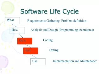
Figure 15-1, Simple life cycle for software development. Software development «include» «include» «include» Problem definition System development System operation Client Project manager Developer Administrator End user
Figure 15-2, Simple life cycle for software development. Problem System System definition development operation activity activity activity
Figure 15-3, Another simple life cycle. System development activity System upgrade activity Market creation activity
Lessons learned Market survey document document System specification Executable system document Figure 15-4, Entity-centered view of software development. Software Development
Activity Work product Figure 15-5, Activities and products of the simple life cycle of Figure 15-2. Market survey consumes document Problem definition activity produces Specification document consumes System development activity produces Executable system consumes System operation activity produces Lessons learned document
Figure 15-6, Model of the software life cycle. Software Life Cycle Money * Process Group Time Participant * Process * Resource * Work Unit consumed by * * Activity Task Work Product produces
Figure 15-7. Process interrelationships in the IEEE 1074 standard. Development processes Management processes Integral processes Concept Exploration Process System Allocation Process RequirementsProcess ProjectInitiation Process ConfigurationManagement Process DesignProcess ImplementationProcess ProjectMonitoring&Ctrl Process DocumentationDevelopmentProcess InstallationProcess Operation& SupportProcess S/W QualityManagement Process TrainingProcess MaintenanceProcess Verification& Validation Process RetirementProcess
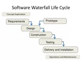
Figure 15-8, The waterfall model of software development is an activity-centered view of the software life cycle. Project Initiation Process Concept Exploration Process System Allocation Process Requirements Process Design Process Implementation Process Verification & Validation Process Installation Process Operation & Support Process
Figure 15-9, V-Model of software development. System Requirements Operation Analysis Software Client Requirements Acceptance Elicitation System Requirements Integration Analysis & Test Component Preliminary Integration Design & Test Detailed Unit Design Test Implementation
Figure 15-10, Boehm’s spiral model (Adapted from [Boehm, 1987]).
Management Unified Process Software Life Cycle Environment Requirements Design Inception Implementation Elaboration Assessment Construction Deployment Transition Figure 15-11, Workflows in the unified software life cycle used by Royce. releases Product * Workflow Cycle * 4 Phase * * Artifact Iteration
Figure 15-12, States of a Software System called phases in the Unified Process. Inception Elaboration Transition Construction
Figure 15-14, Entity-centered life cycle view of the models of the Unified Process. Use case model specified by realized by Analysis model distributed by Design model implemented by Deployment model verified by Implementation model Test model
Figure 15-15, Snapshot of a project issue base. Issues i1 and i5 have been resolved, whereas all other issues are still open. Dependencies among issues indicate that the resolution of an issue can constraint the alternatives for dependent issues. i1:Issue status={Closed} i5:Issue status = {Open} i2:Issue status = {Open} i7:Issue status={Closed} i3:Issue status = {Open} i6:Issue status = {Open}
Figure 15-16, The waterfall model as a special case of the issue-based life cycle model. All issues that belong to the same issue category are contained in the same UML package. In the project status shown in the figure, all the requirements elicitation and analysis issues have been closed; that is, the requirements elicitation and analysis activities have been completed. Req. Elicitation Analysis i1:Issue i5:Issue status={Closed} status={Closed} i2:Issue i7:Issue status={Closed} status={Closed} i3:Issue System Design status={Closed} i6:Issue status = {Open}
Figure 15-17, In a complex project state, all activities can still have some open issues, which means that all activities need to be managed concurrently. Req. Elicitation Analysis i1:Issue i5:Issue status={Open} status={Open} i2:Issue i7:Issue status={Closed} status={Closed} i3:Issue System Design status={Closed} i6:Issue status = {Open}