Download
1 / 54
540 likes | 661 Vues
This presentation by Dr. Nawras Aldibbiat, held on 23rd November 2005, provides an in-depth exploration of Dual Header Pulse Interval Modulation (DH-PIM), a technique essential for advanced optical communication systems. It covers foundational principles, including power spectral density, artificial light interference, and error probabilities in slot and packet systems. The discussion further delves into the bandwidth requirements and multipath propagation challenges faced in optical communications, presenting insights on how DH-PIM offers a promising solution for indoor optical wireless systems.

E N D
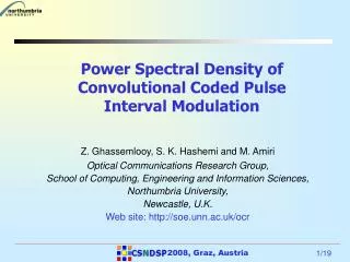
Northumbria Univ. www.unn.ac.uk/ocr Dr. Nawras Aldibbiat 23rd November 2005 Dual Header Pulse Interval Modulation (DH-PIM) Dr. Nawras Aldibbiat Professor Z Ghassemlooy Optical Communications Research Group School of Computing, Engineering & Information Sciences, Northumbria University Email: Nawras.Aldibbiat@unn.ac.uk Tel: 0191 227 3841
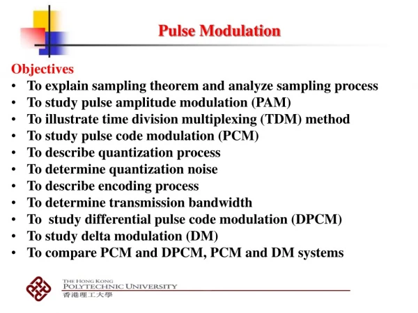
Northumbria Univ. www.unn.ac.uk/ocr Dr. Nawras Aldibbiat 23rd November 2005 Outline of the Presentation • Introduction • DH-PIM principles • Power spectral density • Artificial light interference • Slot & packet error probabilities • Optical power & B/W requirements. • Multipath propagation • Conclusions
Northumbria Univ. www.unn.ac.uk/ocr Dr. Nawras Aldibbiat 23rd November 2005 Introduction DH-PIM was first introduced in 2000: N. M. Aldibbiat & Z. Ghassemlooy: “Dual header-pulse interval modulation (DH‑PIM) for optical communication systems”, CSNDSP 2000, Bournemouth, UK, pp. 147-152, July 2000. Why DH-PIM? Is it ideal for Indoor optical wireless systems?
Northumbria Univ. www.unn.ac.uk/ocr Dr. Nawras Aldibbiat 23rd November 2005 Introduction Directed Hybrid Non-directed Line-of-Site Non-Line-of-Site
Pulse Time Modulation Analogue Digital Isochronous Isochronous Anisochronous Anisochronous PIWM DPWM DPIWM PWM PPM PIM PPM DPPM PFM MPPM DPIM SWFM PCM Northumbria Univ. www.unn.ac.uk/ocr Dr. Nawras Aldibbiat 23rd November 2005 Pulse Time Modulation Tree DH-PIM
Northumbria Univ. www.unn.ac.uk/ocr Dr. Nawras Aldibbiat 23rd November 2005 Pulse Modulation Symbol Structure
Northumbria Univ. www.unn.ac.uk/ocr Dr. Nawras Aldibbiat 23rd November 2005 DH-PIM symbol structure
Northumbria Univ. www.unn.ac.uk/ocr Dr. Nawras Aldibbiat 23rd November 2005 Symbol Length
250 PPM DPIM DH-PIM 1 200 DH-PIM 2 150 Average symbol length [Ts] 100 50 0 3 3.5 4 4.5 5 5.5 6 6.5 7 7.5 8 M [slot] Northumbria Univ. www.unn.ac.uk/ocr Dr. Nawras Aldibbiat 23rd November 2005 Average Symbol Length
DH-PIM requires less bandwidth compared with PPM & DPIM. 32 28 24 20 Normalised bandwidth requirements 16 PPM 12 DH-PIM DH-PIM 2 8 1 DPIM 4 DH-PIM 3 0 3 4 5 6 7 8 M [slot] Northumbria Univ. www.unn.ac.uk/ocr Dr. Nawras Aldibbiat 23rd November 2005 Transmission bandwidth Bandwidth normalised to OOK:
B = 1 MHz r e q 6 5.5 5 4.5 DH-PIM 4 3 3.5 Normalised packet transmission rate 3 DH-PIM 2 2.5 DPIM 2 1.5 DH-PIM 1 PPM 1 0.5 2 3 4 5 6 7 8 9 10 M [bit] Northumbria Univ. www.unn.ac.uk/ocr Dr. Nawras Aldibbiat 23rd November 2005 Transmission Packet Rate
M = 5 800 700 DH-PIM 600 3 500 DH-PIM 2 packet transmission rate [packet/sec] 400 DPIM 300 DH-PIM 1 200 PPM 100 0 1 2 3 4 5 6 7 8 9 10 B [Hz] 6 Northumbria Univ. www.unn.ac.uk/ocr Dr. Nawras Aldibbiat 23rd November 2005 x 10 r e q Transmission Packet Rate - cont.
12 DH-PIM 3 10 8 DH-PIM Normalised transmission capacity 2 6 DPIM 4 DH-PIM 1 2 PPM 0 3 4 5 6 7 8 9 10 M [slot] Northumbria Univ. www.unn.ac.uk/ocr Dr. Nawras Aldibbiat 23rd November 2005 Transmission Capacity
Northumbria Univ. www.unn.ac.uk/ocr Dr. Nawras Aldibbiat 23rd November 2005 DH-PIM system block diagram Transmitter Channel Receiver
Northumbria Univ. www.unn.ac.uk/ocr Dr. Nawras Aldibbiat 23rd November 2005 DH-PIM Transmitter
Northumbria Univ. www.unn.ac.uk/ocr Dr. Nawras Aldibbiat 23rd November 2005 DH-PIM Receiver
1 Input data 0.5 0 0 2 4 6 8 10 12 14 16 t [Sec] 1 Transmitted DH-PIM 0.5 0 0 2 4 6 8 10 12 14 16 t [Sec] 1 Received DH-PIM 0.5 0 Northumbria Univ. www.unn.ac.uk/ocr Dr. Nawras Aldibbiat 23rd November 2005 -0.5 0 2 4 6 8 10 12 14 16 t [Sec] Simulation Waveforms (16-DH-PIM1 )
0.5 Matched Filter output 0 -0.5 0 2 4 6 8 10 12 14 16 t [Sec] 1 0.5 Received DH-PIM 0 0 2 4 6 8 10 12 14 16 t [Sec] 1 0.5 Output data 0 0 2 4 6 8 10 12 14 16 t [Sec] Northumbria Univ. www.unn.ac.uk/ocr Dr. Nawras Aldibbiat 23rd November 2005 Simulation Waveforms (16-DH-PIM1 ) - cont.
Northumbria Univ. www.unn.ac.uk/ocr Dr. Nawras Aldibbiat 23rd November 2005 Simulation Model
Northumbria Univ. www.unn.ac.uk/ocr Dr. Nawras Aldibbiat 23rd November 2005 Power Spectral Density
2 10 8-DH-PIM 2 Predited result 0 Simulated result 10 -2 10 PSD [Watts/Hz] -4 10 -6 10 -8 10 0 1 2 3 4 F [Hz] Northumbria Univ. www.unn.ac.uk/ocr Dr. Nawras Aldibbiat 23rd November 2005 Power Spectral Density - cont.
Northumbria Univ. www.unn.ac.uk/ocr Dr. Nawras Aldibbiat 23rd November 2005 Power Spectral Density - cont. DH-PIM1
Northumbria Univ. www.unn.ac.uk/ocr Dr. Nawras Aldibbiat 23rd November 2005 Power Spectral Density - cont. DH-PIM2
10 DH-PIM 9 5 8 7 DH-PIM 4 6 r o n - 5 C DH-PIM D 3 P 4 3 DH-PIM 2 2 DH-PIM 1 1 0 2 3 4 5 6 7 8 M [bit] Northumbria Univ. www.unn.ac.uk/ocr Dr. Nawras Aldibbiat 23rd November 2005 DC component of the PSD
1 0.8 DH-PIM 1 0.6 DH-PIM r 3 o n - t 0 l s P 0.4 DH-PIM 5 0.2 0 2 3 4 5 6 7 8 M [bit] Northumbria Univ. www.unn.ac.uk/ocr Dr. Nawras Aldibbiat 23rd November 2005 Slot component of the PSD
Northumbria Univ. www.unn.ac.uk/ocr Dr. Nawras Aldibbiat 23rd November 2005 Artificial light interference • Artificial light (e.g. Fluorescent) induces periodic interference that contain harmonics at low frequencies • This interference can be reduced by employing a high-pass filter, but … • this results in baseline wander, which is more severe in modulation schemes that contain high power at DC and low frequencies. Therefore … • there is a trade-off between the extent of artificial light interference rejection and the severity of baseline wander.
1 M = 4 (L = 16) 0.8 0.6 PSD (linear units) 0.4 OOK-NRZ DH-PIM (alpha=2) DH-PIM (alpha=1) 0.2 DPPM 0 0 1 2 3 4 5 6 Normalised frequency (f / R ) b Northumbria Univ. www.unn.ac.uk/ocr Dr. Nawras Aldibbiat 23rd November 2005 Artificial light interference PSD for OOK, DPPM and DH-PIM (=1 and = 2) for M = 4
Northumbria Univ. www.unn.ac.uk/ocr Dr. Nawras Aldibbiat 23rd November 2005 Artificial light interference – cont. Simulation block diagram 1 • Assumptions: • a rectangular pulse shape • an equal average transmitted optical power for all systems
Northumbria Univ. www.unn.ac.uk/ocr Dr. Nawras Aldibbiat 23rd November 2005 Artificial light interference – cont. • 8-DH-PIM1 on non-dispersive channel • For fc/Rb< 0.01, an additional 5 dB of power is required when Rb is increased from 1 Mbps to 10 Mbps and from 10 Mbps to 100 Mbps. • for fc/Rb> 0.01, the power requirement starts to increase more swiftly for 1 Mbps than 10 Mbps and 100 Mbps.
Northumbria Univ. www.unn.ac.uk/ocr Dr. Nawras Aldibbiat 23rd November 2005 Artificial light interference – cont. • 8-DH-PIM1 assuming multipath propagation • Normalised delay spread (NDS) = RMS delay spread (DT) / Bit rate (RB) • For fc/Rb < 0.01, the power requirements are constant for all values of NDS with NDS of 0.1 displaying the highest value • For fc/Rb > 0.01, the power requirements increase exponentially reaching the same value for fc/Rb > 0.5
Northumbria Univ. www.unn.ac.uk/ocr Dr. Nawras Aldibbiat 23rd November 2005 Artificial light interference – cont. • Rb= 1Mbps and no multipath dispersion • DH-PIM1 has marginally higher power penalty than DPIM and PPM but lower than OOK • For fc/Rb = 0.1: DH-PIM displays far less power penalty than OOK but 1.6 dB and 1 dB additional power penalty compared with PPM and DPIM, respectively. This is because at low frequency region, the PSD of DH-PIM is higher than PPM and DPIM and lower than OOK
Northumbria Univ. www.unn.ac.uk/ocr Dr. Nawras Aldibbiat 23rd November 2005 Slot/packet error rate • Assumptions: • The input signal is composed of binary independent, identically distributed bits of ‘1’s and ‘0’s • The matched filter is sampled at the slot frequency fs • The channel is a distortion free channel • No bandwidth limitations imposed by the transmitter and receiver • The dominant noise source is the background shot noise • No interference due to artificial light • Packet length G= 1KB bits • Equal occurrence of H1 and H2
: average transmitted optical power, R: a photodetector responsivity. 0 < k < 1 is the threshold factor. Northumbria Univ. www.unn.ac.uk/ocr Dr. Nawras Aldibbiat 23rd November 2005 Slot error rate for DH-PIM is given by: for PIM: where
0 10 -1 10 -2 10 -3 10 -4 10 -5 10 -5 -3 -1 1 3 5 7 9 11 Northumbria Univ. www.unn.ac.uk/ocr Dr. Nawras Aldibbiat 23rd November 2005 Slot error rate Vs. SNROOK • 12,000 consecutive random bits were used in simulation. • Slot error rate is shown down to 10-5due to computational power. DH-PIM (alpha=1) *** Simulated __ Predicted • The higher the M, the • better the slot error rate • performance. • Simulated results • match the predicted ones. M = 3 Slot error rate M = 4 M = 5 SNR [dB] O O K
Northumbria Univ. www.unn.ac.uk/ocr Dr. Nawras Aldibbiat 23rd November 2005 Slot error rate - cont. L=16 slot (M=4 bits) 0 10 -2 • DH-PIM and DPIM offer • improved slot error • performance compared with • OOK, but inferior to that of • PPM. • At slot error rate of 10-9 PIM • and DH-PIM ( = 1) display • an improvement of ~5 dB • over DH-PIM ( = 2). 10 OOK PIM PPM -4 10 Slot error rate -6 10 DH-PIM (alpha=1) DH-PIM -8 10 (alpha=2) -10 -8 -6 -4 -2 0 2 4 6 8 10 12 14 SNR [dB] O O K
The packet error rate is given by Northumbria Univ. www.unn.ac.uk/ocr Dr. Nawras Aldibbiat 23rd November 2005 Packet error rate • For DH-PIM: • For DPIM: Gis the packet length in bits.
Northumbria Univ. www.unn.ac.uk/ocr Dr. Nawras Aldibbiat 23rd November 2005 Packet error rate Vs. SNROOK L=16 slots (M=4bits) 0 10 • G= 1KB bits. • DH-PIM and DPIM offer • improved packet error • performance compared • with OOK, but inferior to that • of PPM. • At packet error rate of 10-6 • PIM and DH-PIM ( = 1) • display an improvement of • ~5 dB over DH-PIM ( = 2). -1 10 OOK PIM PPM -2 10 -3 10 Packet error rate DH-PIM (alpha=2) -4 10 DH-PIM (alpha=1) -5 10 -6 10 0 2 4 6 8 10 12 14 SNR [dB] O O K
0 10 M=4 & alpha=1 -1 10 M=4 & alpha=2 M=5 & alpha=1 M=5 & alpha=2 -2 10 -3 10 Packet error rate -4 10 -5 10 -6 10 0 2 4 6 8 10 12 14 SNR [dB] O O K Northumbria Univ. www.unn.ac.uk/ocr Dr. Nawras Aldibbiat 23rd November 2005 DH-PIM packet error rate - cont. DH-PIM • G= 1KB bits • The higher the M, the • better the packet error • rate performance. • The smaller the , the • better the packet error • rate performance.
Northumbria Univ. www.unn.ac.uk/ocr Dr. Nawras Aldibbiat 23rd November 2005 Retransmission Simulation block diagram: Parameters: ret = 1, 3, 4 and 5 Majority decision scheme retransmission rate M = 2, 3, 4 and 5 Bit resolution α = 1 and 2 No of slots in the wide pulse of the header N_bits = 60,000 No of bits in the simulation K = 50% Threshold factor Rb = 1 MB/S Bit rate η = 6.4000e-023; One-sided PSD of the noise I_bg = 200 µAmp Background noise current R = 0.6 Receiver responsivity. SNR = -10:14 signal-to-noise ratio in dB.
Northumbria Univ. www.unn.ac.uk/ocr Dr. Nawras Aldibbiat 23rd November 2005 Retransmission - cont. • At SER = 10-4 • DH-PIM with Ret = 3 gives an improvement of ~ 1 dBm over standard DH-PIM • DH-PIM with Ret = 5 gives an improvement of ~ 2 dBm over standard DH-PIM
Northumbria Univ. www.unn.ac.uk/ocr Dr. Nawras Aldibbiat 23rd November 2005 Retransmission - cont. • At SER = 10-4 • DH-PIM with Ret = 3 gives an improvement of ~ 1 dBm over standard DH-PIM • DH-PIM with Ret = 5 gives an improvement of ~ 2 dBm over standard DH-PIM
4 DH-PIM (alpha=1) L=2 DH-PIM (alpha=2) PIM 2 OOK 4 2 2 100% 0 4 50% 4 8 -2 33.33% 16 25% 8 Normalised optical-power requirement [dB] 8 -4 32 16 16 64 32 -6 128 32 -8 64 256 64 -10 1 2 3 4 5 6 7 8 9 Normalised bandwidth requirements Northumbria Univ. www.unn.ac.uk/ocr Dr. Nawras Aldibbiat 23rd November 2005 Optical Power Vs. bandwidth requirements • The average optical power • is calculated at packet • error rate of 10-6 for a • packet length of 1KByte. • To minimise the optical • power and bandwidth, the • parameter combinations • are: • DH-PIM (L=16, =1) • DH-PIM (L=64, =2) • DPIM L = 16
Northumbria Univ. www.unn.ac.uk/ocr Dr. Nawras Aldibbiat 23rd November 2005 Multipath Propagation
Segment of m slots: { s , s , ..., s } ,1 +2 + i i i m Start a Select Hence H & start of 2 full DH-PIM symbol. Leading slot = 0 Next slot = 1? Reset to start of Yes ? No segment. No Yes Could be H1 or H2 Count No. of 0's Complet symbol? Count No. of 0's No No Acceptable? Yes No Yes Acceptable? Calculate prob of Set initial prob occurrence Yes Calculate prob of occurrence Calculate prob of '1' detected at start of full DH-PIM symbol occurrence At least 3 more slots? No Calculate prob for Yes '1' or '10' or '11' & multiply Acceptable header? No Yes Calculate prob of All done occurrence & Calculate no. of 0's multiply Yes Calculate prob of '1' detected? Acceptable? occurrence & Yes multiply No No Invalid segment prob = 0. Northumbria Univ. www.unn.ac.uk/ocr Dr. Nawras Aldibbiat 23rd November 2005 Multipath Propagation
32-DH-PIM , R = 1 Mbps -6 1 b x 10 8 _____ D = 0.001 __ __ T D = 0.01 7 ___ _ T D = 0.1 T ........ D = 0.2 6 T 5 Cascaded system impulse response 4 3 2 1 0 0 1 2 3 4 5 6 7 8 9 T Northumbria Univ. www.unn.ac.uk/ocr Dr. Nawras Aldibbiat 23rd November 2005 s Impulse Response
-3 -3 x 10 x 10 1.2 1 1 0.8 0.8 NDS = 0.01 NDS = 0.1 0.6 0.6 0.4 0.4 0.2 0.2 0 0 1 2 3 4 5 6 7 8 1 2 3 4 5 6 7 8 Northumbria Univ. www.unn.ac.uk/ocr Dr. Nawras Aldibbiat 23rd November 2005 Diffuse Systems - Eye Diagram
11 L = 32 ____ DH-PIM 9 1 DH-PIM ....... 2 7 5 3 Normalised optical power requirements (dB) L = 4 1 8 4 -1 8 16 -3 16 32 -5 32 -7 -3 -2 -1 0 10 10 10 10 RMS delay spread / T Northumbria Univ. www.unn.ac.uk/ocr Dr. Nawras Aldibbiat 23rd November 2005 b Optical Power Requirements
12 L = 32 10 DH-PIM 1 8 DH-PIM 2 DPIM 6 PPM OOK 4 2 Normalised optical power requirements (dB) 0 -2 -4 -6 -8 -10 -3 -2 -1 0 10 10 10 10 RMS delay spread / T Northumbria Univ. www.unn.ac.uk/ocr Dr. Nawras Aldibbiat 23rd November 2005 b Optical Power Requirements - cont.
DH-PIM DH-PIM 2 1 12 _____ L = 4 .......... L = 8 --o--o-- L = 16 10 __ __ L = 32 8 Normalised optical power penalty (dB) 6 4 2 0 -3 -2 -1 0 10 10 10 10 RMS delay spread / T Northumbria Univ. www.unn.ac.uk/ocr Dr. Nawras Aldibbiat 23rd November 2005 b Optical Power Penalty
L = 32 14 DH-PIM 1 DH-PIM 12 2 DPIM PPM 10 OOK 8 Optical power Penalty (dB) 6 4 2 0 -3 -2 -1 0 10 10 10 10 RMS delay spread / T Northumbria Univ. www.unn.ac.uk/ocr Dr. Nawras Aldibbiat 23rd November 2005 b Optical Power Penalty - cont.