MAE 5130: VISCOUS FLOWS
MAE 5130: VISCOUS FLOWS. Introduction to Boundary Layers October 26, 2010 Mechanical and Aerospace Engineering Department Florida Institute of Technology D. R. Kirk. EFFECTS OF VISCOUS FORCES ON FLOW REGIMES IN A CHANNEL. FLAT PLATE ANALYSIS.

MAE 5130: VISCOUS FLOWS
E N D
Presentation Transcript
MAE 5130: VISCOUS FLOWS Introduction to Boundary Layers October 26, 2010 Mechanical and Aerospace Engineering Department Florida Institute of Technology D. R. Kirk
FLAT PLATE ANALYSIS • Fluid shears against the plate due to no-slip condition • Causes a frictional drag force • Velocity distribution, u(y) at any downstream position has smooth drop-off at wall • To satisfy conservation of mass, streamlines deflected away from plate • Deflection is relatively small so that pressure remains approximately constant • Shear layer thickness is defined as u/U=0.99=d99% • Displacement thickness, d*: amount that streamlines deflect outside of shear layer (Y-H)
LAMINAR VERSUS TURBULENT FLOW • Two types of viscous flows • Laminar: streamlines are smooth and regular and a fluid element moves smoothly along a streamline • Turbulent: streamlines break up and fluid elements move in a random, irregular, and chaotic fashion
LAMINAR VERSUS TURBULENT FLOW All B.L.’s transition from laminar to turbulent Turbulent velocity profiles are ‘fuller’ cf,turb > cf,lam
LAMINAR TO TURBULENT TRANSITION • Stable laminar flow near leading edge • Unstable 2D Tollmien-Schlichting waves • Development of 3D unstable waves and ‘hairpin’ eddies • Vortex breakdown at regions of high localized shear • Cascading vortex breakdown into fully 3D fluctuations • Formation of turbulent spots at locally intense fluctuations • Coalescence of spots into fully turbulent flow • Smoke-flow visualization of flow with transition induced by acoustic input • ReL = 814,000 • f = 500 Hz
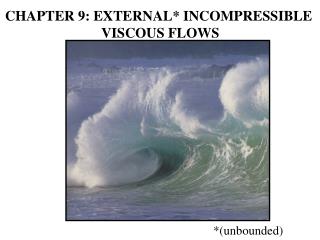
EXAMPLE OF FLOW SEPARATION • Velocity profiles in a boundary layer subjected to a pressure rise • (a) start of pressure rise • (b) after a small pressure rise • (c) after separation • Flow separation from a surface • (a) smooth body • (b) salient edge
EXAMPLE: FLOW SEPARATION • Key to understanding: Friction causes flow separation within boundary layer • Separation then creates another form of drag called pressure drag due to separation
RELEVANCE OF FRICTION ON AN AIRFOIL Flow very close to surface of airfoil is Influenced by friction and is viscous (boundary layer flow) Stall (separation) is a viscous phenomena Flow away from airfoil is not influenced by friction and is wholly inviscid
EXAMPLE: AIRFOIL STALL • Key to understanding: Friction causes flow separation within boundary layer • B.L. either laminar or turbulent • All laminar B.L. → turbulent B.L. • Turbulent B.L. ‘fuller’ than laminar B.L., more resistant to separation • Separation creates another form of drag called pressure drag due to separation • Dramatic loss of lift and increase in drag
EXAMPLE: AIRFOIL STALL Lift Angle of Attack, a
COMPARISON OF DRAG FORCES d d Same total drag as airfoil
INCOMPRESSIBLE VS. COMPRESSIBLE DEFINITIONS Incompressible Compressible
ALTERNATE PHYSICAL INTERPRETATIONS OF d*, q, and q* • The inviscid flow above the boundary layer in the picture on the left would reach to the position d* if it were continued toward the wall until the same flow rate was achieved Same mass flow
ALTERNATE PHYSICAL INTERPRETATIONS OF d*, q, and q* • For internal flow applications, most important characteristic is effect of displacement thickness on core flow, which can be thought of as a flow blockage • Representation on right has same core velocity and volume flow, but occurs in a channel of reduced height, Weff, compared with actual geometry W
ALTERNATE PHYSICAL INTERPRETATIONS OF d*, q, and q* • Physical interpretation of displacement thickness, d* by considering mass flow rate that would occur in an inviscid flow which has velocity UE and density rE, and comparing this to actual, viscous, situation • In figure rEUEd* is the defect in mass flow due to flow retardation in boundary layer • Effect on flow outside boundary layer is equivalent to displacing the surface outwards, in the normal direction, a distance d* • For a given rEUE, effective width of a 2D channel is reduced by sum of d*upper and d*lower
ALTERNATE PHYSICAL INTERPRETATIONS OF d*, q, and q* • Quantity rEUE2q represents defect in streamwise momentum flux between actual flow and a uniform flow having density rE and velocity UE outside boundary layer • Can be regarded as being produced by extraction of flow momentum and is related to drag
ALTERNATE PHYSICAL INTERPRETATIONS OF d*, q, and q* • Measures defect between flux of kinetic energy (mechanical power) in the actual flow and a uniform flow with UE and rE the same as outside the boundary layer • Defect can be regarded as being produced by extraction of kinetic energy • Power extracted is linked to device losses, and kinetic energy thickness is a key quantity in characterizing losses is internal flow devices
EXAMPLE: 2D STRAIGHT DIFFUSERS • Function of diffuser is to change a major fraction of flow KE into static pressure and to decrease velocity magnitude • AR = W2/W1 • Non-dimensional length is N/W1 • Diffuser opening angle is tan(q)=(AR-1)(2N/W1) • For ideal flow, Cp,i=1-1/AR2 • Compare prior to AA and after AA, significant deviation from predicted flow behavior