Light and Matter For Computer Graphics
370 likes | 504 Vues
This overview provides a high-level introduction to key concepts in light and matter as applied in computer graphics. It explores optics, material properties, and various phenomena such as reflection and transmission. The lecture differentiates between types of reflection (specular, diffuse, mixed) and transmission, while also covering the importance of refraction and the index of refraction. Understanding these elements is crucial for creating realistic images in computer graphics, where the manipulation of light plays a pivotal role in visual representation.

Light and Matter For Computer Graphics
E N D
Presentation Transcript
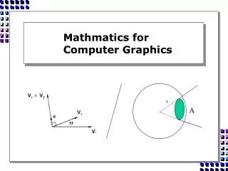
Light and MatterFor Computer Graphics Comp 770 Lecture Spring 2009
Overview • A very high-level introduction to some concepts and definitions underlying image synthesis. • Optics • Materials and Surfaces • Radiometry and Photometry • Color • Energy Transport
Optics • The study of light has 3 sub-fields. • Physical optics: study of the wave nature of light. • Geometric optics: study of the particle nature of light. • Quantum optics: study of the dual wave-particle nature of light and attempt to construct unified theories to support duality. Wave “packets” called photons. • Computer graphics most concerned with geometric optics (but need some of the others, too).
Reflection and Transmission • Reflection: “process whereby light of a specific wavelength incident on a material is at least partly propagated outward by the material without change in wavelength.” • Transmission (or refraction): “process whereby light of a specific wavelength incident on the interface (boundary) between two materials passes (refracts) through the interface without change in wavelength.” (Definitions from Glassner1995).
Types of Reflection • Specular (a.k.a. mirror or regular) reflection causes light to propagate without scattering. • Diffuse reflection sends light in all directions with equal energy. • Mixed reflection is a weighted combination of specular and diffuse.
Types of Reflection • Retro-reflection occurs when incident energy reflects in directions close to the incident direction, for a wide range of incident directions. • Gloss is the property of a material surface that involves mixed reflection and is responsible for the mirror like appearance of rough surfaces.
Types of Gloss • Gloss factors measured by the ratio of energy () in the reflected and incident directions for certain standard angles (i and r). • Specularity measures the brightness of a highlight: r /i(i = r = 60°). • Sheen measures the brightness of glancing highlights: r /i (i = r = 85°).
Types of Gloss • Contrast is the brightness of a glancing highlight relative to the brightness in the surface normal direction r /n. (i = r = 85°). • Distinctness of Image measures the clarity of the highlight or the sharpness of its borders: dr / dr , or the rate of change of reflected energy with reflected direction. • Absence of Bloom measures the haziness around the highlight: r2 /r1, where r1 and r2 are only a few degrees different.
N’ N’ I R Computing The Specular Reflection Vector N I R Given: I, N, R are coplanar. IN = R N N’ = (I N)N From the parallelogram shown at right, see: R + I = 2N’ Or R = 2N’ – I = 2(I N)N - I i r
Types of Transmission • Specular transmission causes light to propagate w/o scattering, as in clearglass. • Diffuse transmission sends light in all directions with equal energy, as infrosted glass. • Mixed transmission is a weighted combination of specular and diffuse transmission.
Index of Refraction • The speed of light is not the same in all media. • Reference medium is a perfect vacuum. • IOR: i() = c / v. c = speed of light in vacuum, v is speed of light of wavelength in the medium. • Surface where two media touch called the interface. • Light appears to bend when passing through the interface, due to change in speed. • Amount of bending, or refraction, determined by the IOR of both materials.
N I i t T sint Snell’s Law of Refraction • Governs the geometry of refraction. i()sini = t()sint i = IOR of incident medium t = IOR of medium into which the light is transmitted • If the light is transmitted intoa denser medium, it is refracted toward the normal of the interface. • If the light is transmitted into a rarer medium, it is refracted away from the normal of the interface. sini
Total Internal Reflection • At some angle, called the critical angle, light is bent to lie exactly in the plane of the interface. • At all angles greater than this, the light is reflected back into the incident medium: total internal reflection (TIR). • Snell’s law gives critical angle c i()sinc = t()sin( / 2) sinc = t () / i()
N I R i I|| T -M I M T|| t T Computing The Specular Transmission Vector
Surface Models • Perfect mirrors and reflections don’t exist. • Perfect transmission requires a perfect vacuum. • Real surfaces have some degree of roughness. • Even most basic simulation must account for specular and diffuse reflection / transmission. • More realism requires accounting for more factors. • Wavelength dependence: dispersion, diffraction, interference • Anisotropy: angular-dependence of reflectance. • Scattering: absorption and re-emission of photons.
Basic Surface Models • Non-physically based, as used in OpenGL. • Materials have ambient, diffuse, and specular colors. • Ambient is a very coarse approx. Of light reflected from other surfaces. (Global illumination). • Diffuse usually just the “color” of the surface. • Specular determines highlight color.
What’s Missing? • What we’ve seen so far is just the basics of geometric optics. • Enough for classical ray tracing, Phong illumination model. • To get much better, we need more: • Better modeling of surface properties. • Wavelength dependence. • Radiometry / Photometry. • Energy Transport.
shadow shadow Masked Light Surface Roughness • At a microscopic scale, all real surfaces are rough: • Cast shadows on themselves: • “Mask” reflected light:
Surface Roughness • Notice another effect of roughness: • Each “microfacet” is treated as a perfect mirror. • Incident light reflected in different directions by different facets. • End result is mixed reflectance. • Smoother surfaces are more specular or glossy. • Random distribution of facet normals results in diffuse reflectance.
Reflectance Distribution Model • Most surfaces exhibit complex reflectances. • Vary with incident and reflected directions. • Model with combination: • + + = specular + glossy + diffuse = reflectance distribution
Anisotropy • So far we’ve been considering isotropic materials. • Reflection and refraction invariant with respect to rotation of the surface about the surface normal vector. • For many materials, reflectance and transmission are dependent on this azimuth angle: anisotropic reflectance/transmission. • Examples?
BRDF • Bidirectional Reflectance Distribution Function • (x, i, o) • x is the position. • i = (i, i) represents the incoming direction. (elevation, azimuth) • o = (o, o) represents the outgoing direction (elevation, azimuth)
Properties of the BRDF • Dependent on both incoming and outgoing directions: bidirectional. • Always positive: distribution function. • Invariant to exchange of incoming/outgoing directions: reciprocity principal. • In general, BRDFs are anisotropic.
Dimensionality of BRDF • Function of position (3D), incoming, outgoing directions (4 angles), wavelength, and polarization. • Thus, a 9D function! • Usually simplify: • Ignore polarization (geometric optics!). • Sometimes ignore wavelength. • Assume uniform material (ignore position). • Isotropic reflectance makes one angle go away.
Radiometry • Radiometry: Science of measurement of light. • Measurements are purely physical. • Discusses quantities like radiance and irradiance, flux, and radiosity. • Need some radiometry to go into more detail about BRDF. • Combine with light transport theory and optics to derive radiosity computations. • More in later lectures and in COMP238.
Radiometry vs. Photometry • Photometry: Science of human perception of light. • Perceptual analog of Radiometry. • All measurements relative to perception. • More in COMP238
Color • If we stopped here we’d have grayscale images. • Color is determined by the wavelength of visible light. • Can still use geometric optics. • But need to account for wavelength in reflectance (BRDF) and index of refraction. • What natural phenomena can you think of that are wavelength dependent?
Sampling Wavelength • We could try to compute image for every possible wavelength and then combine. • Would take forever. • Sample a representative set of wavelengths. • How many samples? • Where?
Where to Sample? • Photometry tells us that some wavelengths are more important than others to human perception. • Human response curve looks something like this:
Where to Sample? • So, pick a few samples wavelengths. • Compute an image for each. • Reconstruct with basis functions. • Weight of each sample determined by human response curve. • (Also need colorspace transformations). • More in COMP238.
Light Transport • To compute images, we need to simulate transport of light around a scene. • Transport theory. • Analysis techniques for flow of moving particles in 3D. • Largely developed for neutrons in atomic reactors. • Can be applied to traffic flow, gas dynamics. • Most importantly, can be applied to light. • Simulation techniques. • Ray tracing. • Radiosity. • Combinations and variations.
Local vs. Global Illumination • Radiosity and ray tracing simulate global illumination. • Account for light transport between objects. • Not just between light sources and objects: local illumination. • Don’t need global illumination to use the concepts of geometric optics, surface modeling, and BRDF. • Have been used to create diverse shading models. • Simplest and most common is Phong. • Next lecture: shading models.
For Next Time… • Read: • Henri Gouraud, “Continuous Shading of Curved Surfaces”. IEEE Transactions on Computers; June 1971. • Bui Tuong Phong, “Illumination for Computer Generated Pictures”. Communications of the ACM; June 1975. • James F. Blinn, “Models of Light Reflection for Computer Synthesized Pictures.” Computer Graphics (SIGGRAPH 1977).
References • Glassner, Principles of Digital Image Synthesis, Volume Two. • Highly detailed and low level. • Cohen and Wallace, Radiosity and Realistic Image Synthesis. • Bastos dissertation, ftp://ftp.cs.unc.edu/pub/publications/techreports/00-021.pdf
More Detail: Scattering • When a photon hits an atom, one of two things happens: • Absorption: the photon (energy) is converted into another form of energy. • Scattering: the photon is immediately re-emitted in a new direction.