Download
1 / 1
10 likes | 100 Vues
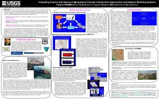
Investigating how one structure shaking affects another nearby structure during earthquakes using Kinemetric triaxial sensors and data analysis in Matlab. Collaboration between NEES@UCLA team and University of Nevada, Reno.

E N D
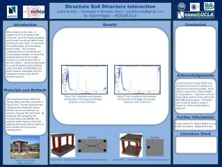
Structure Soil Structure Interaction Justin Kunert – University of Nevada, Reno – justinkunert@gmail.com Dr. Robert Nigbor– NEES@UCLA Introduction Materials and Methods Figure One: Garner Valley Test Site Results Top Slab Top Slab Figure Four: Smaller structure and sensor arrangement. Figure Five: Larger Structure and sensor arrangement. Conclusion Acknowledgements Further Information Literature Cited When viewing a city, town, or neighborhood, it is common that structures, such as bridges, buildings, and houses, are all built within close proximity to each other. In the event of an earthquake, all the buildings would shake. This common understanding is inconsistent with current seismic design, for which the analysis is based off of a single structure on a flat surface with no ground rotation. Using two structures in a real life situation at the Garner Valley Test Site, the NEES@UCLA team hopes to investigate how the shaking of one structure effects another structure. Figure Two: Amplitude ratio between Figure Three: Amplitude ratio between the top slab of the larger and smaller the top slab of the larger and smaller structure in the X direction. structure in the Y direction. I would first like to thank NEES and the National Science Foundation for making this research possible. Much thanks is given to Dr. Robert Nigbor for his guidance. I also want to thank Erica Eskes and the entire staff at the NEES@UCLA program. And lastly, much credit is owed to Jackson English for all of his help with the research. Two simple structures inhabit the Garner Valley Test Site, as shown in Figure One. The two structures are equipped with Kinemetrictriaxial sensors at various locations, as shown in Figures Two and Three. By analyzing and comparing the acquired data using Matlab, the research team hopes to show that adjacent structures have an affect on each another during a ground shaking event. Please contact Dr. Robert Nigbor for any further information: Nigbor@ucla.edu Sensors