Understanding Constant Concentration and Injection Well Dynamics in Groundwater Models
This resource delves into the principles of constant concentration and injection well management within groundwater models, focusing on the recharge dynamics at boundary conditions or within model interiors. It addresses mass flux considerations, chemical reaction impacts, and numerical challenge analysis, particularly regarding Peclet number and numerical error in remediation scenarios. Example problem sets illustrate breakthrough curve generation under varying assumptions, enhancing comprehension of the interaction between source terms and chemical behavior in confined and unconfined layers.

Understanding Constant Concentration and Injection Well Dynamics in Groundwater Models
E N D
Presentation Transcript
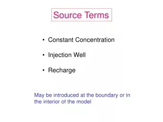
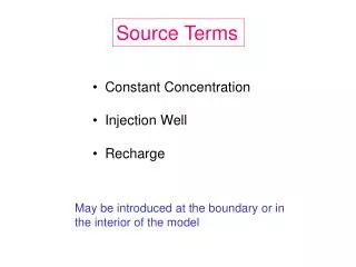
Source Terms • Constant Concentration • Injection Well • Recharge May be introduced at the boundary or in the interior of the model
Q Constant Concentration (Z&B, p. 283) cs e.g., NAPL source area at boundary
Injection Well Qcs well
Recharge R, cs Mass Flux = R (x y)cs
Problem Set #3 Source Terms and Chemical Reactions • Constant Concentration • Injection Well • Recharge • retardation • 1st order decay
Confined layers Problem Set #3 Two Layers This screen shows a constant concentration source. Contours of head are also shown.
Note the water table Flow field for an unconfined upper layer with areal recharge and a recharge source cell.
Problem Set #3 Parts 1 and 2: Produce breakthrough curves under different assumptions about the source term and chemical reactions.
Numerical error caused by high Peclet number Problem Set #3 – Part 3 - Remediation TVD Solution
Numerical error caused by high Peclet number Problem Set #3 – Part 3 - Remediation TVD Solution
Cr < 1 Courant Number Pe < 4 Peclet Number
50 m grid Pumping well is represented by 4 nodes
TVD solution 50 m grid spacing upper left node in the pumping complex Peclet number = 2.5 100 m grid spacing Peclet number = 5
TVD Solution 50 m grid – near center of pumping compex 100 m grid