Download
1 / 38
380 likes | 438 Vues
Learn about spherical deflection plates, detectors, quadrispheric plates, and 3D velocity distributions in this overview of electrostatic analyzers and their use in observing solar wind properties. Discover the challenges and advancements in data collection and analysis for space research.

E N D
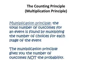
The principle of electrostatic analyzers • Spherical deflection plates (radius R, plate distance d) with an applied voltage (U) let charged particles (mass m, ion charge q, velocity v) pass if their energy/charge (E/q) fits, i.e., if • E/q (= m/2 * V2/q) = UR/2d. • Detectors at the exit of the plates count the successful particles. • Quadrispheric plates with several detectors allow determination of one angle of incidence. • Rotation of the detector, e.g., on a spinning spacecraft, allows determination of the other angle of incidence. • The voltage is stepped through and the successful particles per step are counted. • This way, the particle fluxes of all energy/charge values at all angles of incidence can be measured and a 3D velocity distribution function can be derived.
One of the first E/Q spectra, proving the existence of the solar wind Gringauz (1960) and finally Neugebauer and Snyder (1962) observed the solar wind, using very simple plasma detectors on board interplanetary spacecraft
The ion instruments on Helios 1&2, built at MPE Garching (H. Rosenbauer, PI). Left: a hemispherical analyzer, using an elctrometer for counting charges. Right: a quadrispherical analyzer for counting particles.
The energy-angle dependence requires careful calibrations! The calibration facilitiy at MPE and MPAe
1D ions electrons 3D ions A printout of Helios-E1 raw data
Handplots of raw data were used for daily survey of the solar wind
Solar wind basic properties from daily handplots for the first few solar rotations during appoach of Helios 1 to perihelion.
Proton 3D velocity distributionsfor various wind speeds and distances from the sunas measured by Helios By integration over f(v) vn d3v one gets the „moments“ of the distribution function: n=0 number density n n=1 bulk velocity v n=2 temperature T n=3 heat flux
„Stacked plots“ fo 1D ion raw data shock TD
Discovery of singly ionized Helium ions in the driver gas following an interplanetaryshock wave by Helios 1in January 1977: remnants of cold prominence material. This discovery was only possible when we began routine inspection of E/Q spectra, i.e. raw data! TD H+ He2+ He+ There was only one more such event inJuly 1977. The next one occurrednot earlier than in January 1997, following the halo event on Jan. 6th.
TD Solar wind ion parameter data from Helios E1-I1a/I1b
shock TD speed density temperature direction 24 hrs routine plot of Helios E1 ion data (3 min averages)
shock TD 4 days routine plot of Helios E1 ion data (10 min averages)
shock TD Carrington routine plot of Helios E1 ion data (1 hr averages)
Helios plasma measurements during first approach to perihelion (0.3 AU). The stream fronts become steeper, a surprise for some modelers...
Since 1974, all these various data collections were stored on tapes and printed on paper and microfiches. A major problem: the data had to be adjusted to at least five subsequent computer generations. Presently, the data are available on CD-Rom and on the Internet http://www.linmpi.mpg.de/english/projekte/helios/ http://sprg.ssl.berkeley.edu/htbin/impact/HeliosData.pl http://sec.noaa.gov/ace/ http://umtof.umd.edu/pm
Scheme of the Helios E1 electron instrument (I2), invented by H. Rosenbauer. The trick: no photo electron could ever make it to the detector!
1D ions The electron „Strahl“ electrons 3D ions A printout of Helios-E1 raw data
Electron velocity distributions as measured by Helios E1-I2 Note the “Strahl” of suprathermal electrons flowing along the magnetic field: a Helios discovery.
STEREO spacecraft: Note the electron instrument (SWEA) on the end of the backside boom. It has a field of view of nearly 4П, and it is located in permanent shadow. http://projects.nrl.navy.mil/secchi/spacecraft.html
The problem of electrostatic analyzers The E/q value is not unique: E/q = ½ m v2/nq0. Fortunately, in the solar wind all ions come with about the same velocity vsw (apart from their individual thermal speeds). Therefore, E/q ~ m/nq0
The problem of electrostatic analyzers The m/q values of many fully ionized ions are identical, e.g. 4He2+, 12C6+, 14N7+ ,16O8+,...
The second peak in an E/q spectrum is usually due to Helium ions. That’s why they were clearly discarded when I3 was working in the proton channel. Instrument I3 of Helios-E1was the first solar wind ion mass spectrometer. It measured E/q and, independently v. It could not overcome the m/q problem. In this case, however, the second peakwas due to protons, i.e., a second proton population moving at a different speed!
The SWOOPS ion instrument on Ulysses, built by LANL http://swoops.lanl.gov/
The SWOOPS electron instrument on Ulysses, built by LANL http://swoops.lanl.gov/
An alternative to electrostatic analyzers: the Farady cup. It achieves E/q resolution by varying the voltages on the various grids. This technique was used mainly by the MIT group, e.g., on the Voyager space probes. http://voyager.jpl.nasa.gov/
Electrostatic analyzer complemented with a magnetic deflection system The ions with identical E/q enter a homogeneous magnetic field. There, they are deflected according to their different momenta, i.e. mv/q values. They are then collected in separate detectors. This detector works best if v is identical for all ions, e.g. during the approach to comet Halley (70 km/s)
The Giotto-IMS HIS*, invented by H. Rosenbauer An early 3D study model, plywood... The entrance deflector of the HIS flight unit * HIS: High Intensity Spectrometer
Ion mass spectrum raw data at comet Halley, obtained by the Giotto IMS-HIS instrument
Ion mass spectra obtained inside the coma of comet Halley, by the Giotto IMS-HIS instrument
Ion density profiles during the approach to comet Halley, obtained by the Giotto IMS-HIS instrument
The Giotto-IMS HERS*, invented by M. Neugebauer Principles used: Electrostatic deflection, Post-acceleration, Magnetic deflection * HERS: High Energy Range Spectrometer