Chapter 7 Storage Devices
The Complete A+ Guide to PC Repair 5/e Update. Chapter 7 Storage Devices. Chapter 7 Objectives. Install or replace a floppy drive Define and explain fundamental hard drive terminology Compare and contrast IDE and SCSI technologies Install and configure storage devices


Chapter 7 Storage Devices
E N D
Presentation Transcript
The Complete A+ Guideto PC Repair 5/e Update Chapter 7Storage Devices
Chapter 7 Objectives Install or replace a floppy drive Define and explain fundamental hard drive terminology Compare and contrast IDE and SCSI technologies Install and configure storage devices Troubleshoot storage device problems Perform hard drive preventive maintenance Learn skills for effective communication on the phone
Floppy Drive Overview • The floppy drive allows saving data to disk media. • The floppy drive subsystem consists of three main parts • the electronic circuits or the controller • the 34-pin ribbon cable • the floppy drive • The electronic circuits give the floppy drive instructions. • The electronic circuits can be built into the motherboard or on an adapter. • The floppy cable connects the floppy drive to the electronic circuits.
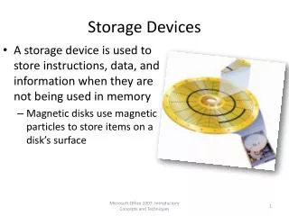
Floppy Media and Construction Disk or Floppy Disk The media inserted in a floppy drive. Write-Protect Window A small window in the corner of a floppy disk with a sliding tab to open or close the window. Read/Write Heads Responsible for placing the data, the 1s and 0s, onto the disk.
Floppy Drive Installation or Replacement Installation of floppy drives is simple after doing the following preliminary homework. Verify that the following are available: 1 • An available drive bay 2 • An available power connection • A motherboard floppy connector or install an additional adapter 3 A floppy cable 4
Floppy Drive Installation Floppy Connector on Motherboard
Floppy Drive Configuration Floppy drive cable
Tech Tip Attach cable correctly or destroy devices and components Most cables that connect to the floppy drive are keyed, but the other end of the cable that connects to the controlling circuits is sometimes not keyed. Devices, adapters, controlling circuits can be damaged if a cable plugs into the connector the wrong way. • Some cables are keyed so they insert only one way into the connector.
Hard Drive Overview Hard drives are a popular device for storing data.
Hard Drive Components Each track is divided into sectors of 512 bytes One corresponding track on all surfaces of a hard drive Concentric circle on a hard drive platter. When a read/write head touches the hard drive platter Write and read the 1s and 0s to and from the hard drive surface Multiple hard metal surfaces contained in the hard drive Read/Write Heads Track Cylinder Head Crash Platters Sector
Hard Drive Geometry Figure 7.3
Hard Drive Geometry Cylinders versus tracks Figure 7.5
Hard Drive Interfaces Overview There are two major hard drive interfaces. IDE (Integrated Drive Electronics) Also known as the ATA (AT Attachment) standard. IDE is most common in home/office computers. SCSI (Small Computer System Interface) SCSI is most common in network servers and network storage.
Architectures • Both parallel architecture and serial architecture used with both IDE and SCSI devices • Parallel • Multiple bits sent simultaneously • Requires precise timing as transfer rates increase • Multiple devices on the same bus (2 with PATA) • Serial • Point-to-point bus where each device has a single connection back to a controller • One bit at a time • Scales easier • Easier to configure.
IDE Types • PATA (Parallel ATA) • Internal devices • Slower that SATA • Traditionally when people spoke of IDE, it was PATA • SATA (Serial ATA) • Internal and external devices • Faster than PATA
PATA Cables • Two types • 40-pin, 40-conductor • Older • Limited to 18 inches • Prone to crosstalk (data from one wire interfering with data in another wire) • 40-pin, 80-conductor • Limited to 18 inches • Required to configure devices as cable select (covered later) • Required with the higher transfer rate devices
PATA Drive • One 40-pin motherboard PATA connector can support up to two PATA devices. • Some cables only have two connectors—one that connects to the motherboard and one that attaches to the PATA device. • If a second device is added, a new cable must be purchased.
SATA (Serial ATA) • SATA – A point-to-point architecture for IDE devices that provides faster access for attached device. • eSATA (external SATA) – A port used to connect external SATA devices to a computer. • SATA-PM (Serial SATA port multiplier) – A device used to connect multiple eSATA devices to a single eSATA port.
SATA A technology used with SATA-PMs that limits the host adapter or port to issuing one command at a time to a single eSATA device. Command-based switching A technology that allows multiple eSATA devices to perform simultaneous operations. It is a faster technology than command-based switching. FIS (Frame Info Structure)
SSD (Solid State Drive) Uses non-volatile Flash memory and no moving parts to store data. It is faster, but more expensive than a hard drive.
SSD • Data on SSDs is handled differently than with a hard drive • Write amplification – The minimum amount of storage space affected by a request to write data on a solid state drive. • Wear leveling - The process of writing and erasing data in different memory blocks of SSDs( solid state drives) to prolong the life of the drive. Methods used: • Software to track usage and direct write operations • Reserved memory bocks to use when a memory block fails • A combination of the first two techniques • Two main technologies: SLC and MLC • SLC (single-level memory cell) - A cell that stores one bit in a memory cell and is more expensive and longer lasting than an MLC. • MLC (multi-level cell) - A cell that stores more than one bit in a memory cell that is used in a SSD (solid state drive). Contrast with SLC.
SCSI (Small Computer System Interface) • SCSI – (pronounced scuzzy) an interface standard that connects multiple small devices to the same adapter via a SCSI bus. • SCSI bus - shared by all devices that attach to one SCSI adapter. • SAS (Serial Attached SCSI) – SAS devices connect in a point-to-point bus. • Used in the enterprise environment where high reliability and high mean time between failures is important.
SCSI Standards Table 7.3
Storage Device Configuration Overview • Configuration of a hard drive usually includes setting jumpers on the drive, terminating properly, and performing a few software commands. • Each drive type has a normal configuration method.
PATA Physical Installation • PATA IDE devices (including hard drives) are simpler to configure than parallel SCSI device. • The steps for installing a PATA device: • Keep drive in the protective antistatic container until you are ready to install. • Use proper anti-static procedures. • Touch the device by the sides • Do not handle the electronics or connectors • Turn off the computer power and remove the power cord. • Configure jumpers • Physically mount and secure the device. Attach cables. • Configure BIOS if needed. • If a hard drive, prepare the drive for data as described later in the chapter.
Tech Tip • Determining which cable select connector to use • When the cable select became a standard with ATA-5, the master connector (the black connector) is at the end of the cable. • The slave connector (the gray one) is in the middle of the connector • The blue connector attaches to the motherboard.
Two PATA devices configured as cable select Figure 7.20
Tech Tip • Closed means jumpered or enabled • Storage device documentation varies in how these are shown. • When documentation shows an option as closed, jumpered, or enabled, this means to put a jumper over the two pins to configure the option.
PATA Installation • Motherboards can have multiple PATA connectors: Primary, Secondary, Tertiary, Quaternary. • The two devices that connect to the cable the connects to the Primary PATA motherboard connector would be known as Primary master and Primary slave. • The two devices that connect to the Secondary connector would be known as Secondary master and Secondary slave.
SATA Physical Installation SATA drives are easy to install • Uses a small 7-pin connector that attaches between the serial ATA controller and the serial ATA drive. • SATA drives do not have any master/slave, cable select, or termination settings.
Installed SATA Hard Drive and Adapter Figure 7.24
SCSI ID Configuration and Termination Each device on a SCSI chain, including the SCSI host adapter is assigned a SCSI ID.
SCSI ID Configuration Power on all external devices before powering on the PC. Wide SCSI devices recognize SCSI IDs 0 through 15. Each SCSI device must have a unique SCSI ID. Standard SCSI devices recognize SCSI IDs 0 through 7.
SCSI Termination • SCSI termination is performed in several different ways • By installing a SIPP • By installing a jumper • By setting a switch • By installing a terminator plug • By installing a pass-through terminator • Through software
SCSI Cables • Parallel SCSI cabling allows multiple devices to be connected to one SCSI host adapter and share the same SCSI bus. • Most internal SCSI-1 and SCSI-2 cables are 50-pin ribbon cables. They are also known as an A cable. • Internal SCSI-3 cables are 68-pin ribbon cables. • When installing multiple SCSI devices, install one device at a time. • Always avoid using the cheaper, thinner SCSI cables. They are more susceptible to outside noise.
External SCSI Cables Figure 7.29
Tech Tip • Use only one technology • If an external drive supports more than one technology, such as eSATA, FireWire, and USB, attach only one type of cable from the drive to the computer.
Laptop Storage Devices • A laptop normally has a PATA or SATA hard drive installed but could have an SSD instead of or in addition to the hard drive. • Two methods are used with hard drives installed in portable computers • Proprietary - the hard drive is installed in a location where it cannot be changed, configured, or moved very easily. • Removable - the hard drive with a laptop is installed or removed through a 44-pin connector.
System BIOS Configuration for Hard Drives • Hard drives are configured through the BIOS Setup program. - IDE hard drives are normally configured using the Auto-Detect feature included with BIOS. This feature automatically determines the drive type for the system. - For SCSI hard drive installation the most common CMOS setting for the hard drive type is type 0 or None.
Hard Drive Preparation Overview Two steps to hard drive preparation
Partitioning • The first step in preparing a hard drive for use in partitioning. • Partitioning a hard drive divides the drive so the computer system sees the hard drive as more than one drive.
Partitioning Information • Disk Administrator- A Windows program that allows testing, configuration, and preventive maintenance on hard drives. • Can also use the diskpart command utility • File system – Defines how data is stored on a drive. Examples of file systems include FAT16, FAT32, exFAT, and NTFS. • Cluster – The minimum amount of space that one saved file occupies.