Internet
Internet. Communications, Networking & Computer Security Sanjay Goel University at Albany. Outline. What is Internet? Internet Protocols Protocol hierarchies The OSI reference model Services in the OSI model. Internet What is it?. It is a network of networks

Internet
E N D
Presentation Transcript
Internet Communications, Networking & Computer Security Sanjay Goel University at Albany
Outline • What is Internet? • Internet Protocols • Protocol hierarchies • The OSI reference model • Services in the OSI model
InternetWhat is it? • It is a network of networks • Any network connected to the internet • Conform to certain naming conventions • Must run the IP protocol • IP protocol is also called Internet dial tone • Internet has a hierarchical topology • End Systems connected to local ISPs through access networks • Access Network examples – LAN, telephone line with a modem, high speed cable networks • Local ISPs connected to regional ISPs, regional ISPs connected to national & international ISPs • Construction analogous with Lego construction
Internet Role • Allows distributed applications to exchange data with each other • Applications include: FTP, Telnet, Mail, WWW, distributed games, video conferencing • Provides two kinds of services • Connection Oriented Service (TCP): Establish connection prior to data exchange, coupled with reliable data transfer, flow control, congestion control etc. • Connectionless Service (UDP): No handshake prior to data exchange, No acknowledgement of data received, no flow/congestion control
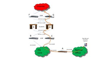
Modem Home Multi-media Ethernet ISP University Security Lan ISP Hosting Platform Origins of Online Content Internet Information Flow
Internet Protocol Hierarchies • Internet is a very complex system • Set of layers and protocols represents the Network Architecture. • Protocols are stacked vertically as series of ‘layers’. • Each layer has a well defined interface. • Allows for easy replacement of layer • Each layer offers Services to layer above, shielding implementation details. • Each layer on one machine communicates with corresponding layer on another machine using Protocol for the Layer.
Internet Layering Principle N+1 PDU (N+1) Entity Service User (N+1) Entity Service User Layer N+1 protocol Layer N Service Access Point (SAP) SDU (N) Entity Service Provider (N) Entity Service Provider Layer N protocol N PDU N PDU PDU - Protocol Data Unit SDU - Service Data Unit • Service = set of primitives provided by one layer to layer above. • Service defines what layer can do (but not how it does it). • Protocol = set of rules governing data communication between peer entities, i.e. format and meaning of frames/packets. • Service/protocol decoupling very important.
Internet Connections & Reliability • Connections • Layers can offer connection-oriented or connectionless services. • Connection-oriented like telephone system. • Connectionless like postal system. • Each service has an associated Quality-of-service (e.g. reliable or unreliable). • Reliability • Reliable services never lose/corrupt data. • Reliable service costs more. • Typical application for reliable service is file transfer. • Typical application not needing reliable service is voice. • Not all applications need connections.
Layer n/n+1 interface Layer n/n+1 interface Layer n protocol Layer n Layer n Layer n-1/n interface Layer n-1/n interface Layer 2/3 interface Layer 2/3 interface Layer 2 protocol Layer 2 Layer 2 Layer 1/2 interface Layer 1/2 interface Layer 1 protocol Layer 1 Layer 1 Physical communications medium Internet Layers, Protocols & Information Flow
Hi TCP Connection Request Hi TCP Connection Response Got the Time? Get http://www.ibm.com/ 8:50 Index.html Protocol Definition • A protocol defines the format and order of messages exchanged between two of more communicating entities as well as the actions taken on the transmission and/or receipt of a message or event.
Host A Host B Examples Message Http, Ftp, Smtp, Telnet Application Layer Application Layer Packet (Bridge) Transport Layer Transport Layer TCP, UDP Port-to-Port Datagram (Router) Network Layer Network Layer IP Host-to-Host Frame (Hub) Link Layer Link Layer Ethernet, FDDI Node-to-Node Physical Network Internet Architecture • Analogous to the mail system in context of layering & standardized protocols.
Application LayerFunction • Implements application protocol • Users invoke applications using this protocol • Application Layer Protocol defines • Types of messages exchanged e.g. request or response • Syntax of the various message types, such as, fields in the messages and how they are delineated • Semantics of the fields i.e. meaning of information in each field • Rules for determining when and how a process sends messages and responds to messages
Application LayerFunction • Different applications use different protocols • Web Servers/Browsers use HTTP • File Transfer Utilities use FTP • Electronic Mail applications use SMTP • Naming Servers use DNS • Interacts with transport layer to send messages • Choose the transport layer protocol • Fix transport layer parameters, such as, buffer/segment sizes
Process TCP/UDP with Buffers and Variables TCP/UDP with Buffers and Variables Process Controlled by Application Developer Controlled by Operating System Controlled by Operating System Controlled by Application Developer HOST HOST Application LayerInterface Socket Socket • Socket is the interface between the application layer and the transport layer • Two parameter are required for identifying receiving process • Host machine identifier - IP Address • Host machine process identifier - Port Internet
Method sp URL sp Version ctr lf Header Field Name Header Field Name : : Value Value cr cr lf lf cr lf Message Body Application LayerFormat Http Request Message Example Http Request Message Format Request Line Get /somedir/page.html HTTP/1.1 Connection: close User-agent: Mozilla Accept: text/html, image/gif, image/jpeg Accept-language: fr (extra carriage return, line feed) • Types of messages • HTTP request, HTTP response, HTTP head Header Lines
Transport LayerFunction • Provides for logical communication between applications running on different hosts • Application multiplexing and demultiplexing • Implemented in the end systems but not in network routers • On sending side • Divides stream of application message into smaller units (packets), • Adds the transport header to each chunk • Sends message to network layer • On receiving side • Takes the header off the message packets • Reassembles the packets in order • Sends message to the application layer • Two internet transport protocols available • TCP, UDP
Transport LayerProtocol: TCP • TCP (Transmission Control Protocol) • Connection Oriented Service (requires handshake) • Duplex • Simplex • Reliable Data Transfer • Guaranteed delivery of packets • Congestion Control • Throttles process when network is congested • No guarantee of a minimum transmission rate • Suitable for reliability critical/ non time critical applications • FTP, SMTP, Telnet, HTTP
Transport LayerProtocol: UDP • Stands for User Datagram Protocol • Lightweight transport protocol • Connectionless (no handshake) • Unreliable data transport service • No acknowlegements (lost packets not resent) • Messages may arrive out of order • No congestion control • Application can pump as many packets over the socket as it chooses • Suitable for loss-tolerant time critical applications • Audio/Video streaming • Internet Telephony
Source Port Number Destination Port Number Sequence Number Acknowledgement Number Header Length Unused URG ACK P S H R S T S Y N F I N Receiver Window Size Source Port Pointer to Urgent Data Options Data 32-bits Transport LayerTCP Example • Source / Destination Port Numbers • Multiplexing / Demultiplexing • Sequence Number & Acknowledgement Number • Congestion Control • Window size • Flow control • Length Field • Length of TCP header in 32-bit words • Unused field is currently unused • Flag Field contains 6 bits • ACK: shows value in acknowledgement field is valid • RST, SYN, FIN bits used for connection setup and teardown • PSH bit indicates data should be passed to upper layer immediately • URG – indicates that there is data in the segment which is marked as urgent • Ptr to urgent data Points to last byte of the urgent data • Options field is used when sender and receiver negotiate the maximum segment size. TCP header HTTP Message Src: 1081 Dst: 80 Chksum: 0xa858 GET /directory/dirsearch.html HTTP/1.1 Host: www.phoenix.co.uk
Network LayerFunction • Provides communication service between two hosts • Transports packets from sending host to receiving host • Encapsulates packets in IP datagram with IP header • Three primary tasks • Path Determination: Determine the route taken by a packet as it flows from sender to receiver • Switching: Arriving packet is moved to the appropriate output link • Call Setup: Handshake prior to routing packets (required by some network architectures) • If addressed to local machine, remove the IP datagram header and pass up to transport layer.
Network LayerProtocols • Network Layer contains several protocols including • Internet Protocol • Address Resolution Protocol (ARP) • Internet Control Message Protocol (ICMP) • Internet Group Message Protocol (IGMP)
Network LayerInternet Protocol • Internet Protocol • Determines the source and destination IP address of all packets • IP address is a unique address on a network assigned to a device • If the packet is meant for a device on the local host IP gets the MAC address for the device and sends it directly to the host • For a remote packet it first looks up the routing table for an explicit route to the network. • If an explicit route is not available it sends it to a default gateway
Version Header Length Type of Service Packet Length (bytes) 16-bit identifier Flags 13-bit Fragm-entation Offset Time to Live Upper Layer Protocol Headerchecksum 32-bit source IP Address 32-bit destination IP Address Options (if any) Data IP datagram header TCP header HTTP Message 32-bits Src: 192.168.0.40 Dst: 192.168.0.50 TTL: 128 Src: 1081 Dst: 80 Chksum: 0xa858 GET /directory/dirsearch.html HTTP/1.1 Host: www.phoenix.co.uk Network LayerInternet Protocol:Example • Version: IP protocol version • Header Length • TOS • Allows different types of IP datagrams to be differentiated • Datagram Length • Length of data + header • Identifiers, Flags Fragmentation offset • Deal with fragmentation • Time-to-live (TTL) • Decremented each time a router processes a datagram Datagram dropped when field is zero • Protocol • Indicates transport level protocol e.g. 6 indicates TCP, 17 indicates UDP • Checksum: Used for error checking • Data – Contains the transport layer segment
Network LayerAddress Resolution Protocol • Translates MAC address to IP addresses and vice-versa • 2 types of ARP packets: replies and requests • Using ARP for each packet causes a 2 packet overhead for each packet • ARP thus caches the packets • Cache flushed at startup • Cache periodically cleaned up • Cache searched prior to sending the ARP request
Network LayerDynamic Host Configuration Protocol • Physical (MAC) addresses identify the hardware and are configured by the manufacturer • Logical (IP) addresses identify the node and are configured by the customer • IP addresses may be reused if a machine is replaced • IP addresses depend on the customers location • Network number • Configuring client nodes is tedious and error-prone
Unicast DHCP relay DHCP server Broadcast network H1 Network LayerDynamic Host Configuration Protocol • DHCP server maintains configuration information about clients • IP addresses • default router • etc. • Clients broadcastto locate server • Server replies withconfiguration information • Client IP addresses may be temporary (leased)
Link LayerFunction • Purpose is to defines the interface between device & network • It contains a driver that is compatible with the network that the device is connected to • Transfers network layer datagrams over a link from node to node • A node is a router or a host • A link is the communication path along two nodes • Link Layer protocol defines the format of the packets exchanged between the nodes • The packets exchanged by link layer are called frames • Each frame typically encapsulates one datagram • e.g. Ethernet, token ring, FDDI, PPP
Link layerHardware Address • Each frame contains the physical address of the hardware of the packet destination. • This physical address is called the Media Access Control (MAC) address and is burned into the network interface card • This is a 12 character hexadecimal number (analogy social security #) • Example: 00:A0:C9:0F:92:A5 • Here the first six digits are the manufacturers ID and the last six digits are the device ID • As each packet arrives at the network interface card the mac address on the packet is compared to the mac address of the device • If the addresses match the packet is accepted
IP Module IP Module Frame Frame Communication Link Transmitting Adapter Receiving Adapter Sending Node Reveiving Node Link LayerServices • Framing and Link Access • Reliable delivery • Flow Control • Error Detection • Error Correction • Two types of services are provided • Half-Duplex and Full-Duplex • Implemented in adapters commonly called Network Interface Cards (NIC)
Link LayerExample • Ethernet is the dominant protocol in the LAN market • Primary factors are cost and complexity • Many topologies of Ethernet • Bus Topology • Star Topology • Supports multiple medium • Coaxial Cable • Copper Wire • Fiber Optic • Can transmit data at different rates • 10Mbps, 100Mbps, 1Gbps
Physical LayerFunction • Accepts IP datagrams and transmits over specific networks. • Maybe a simple device driver (e.g. an Ethernet driver) or a complex subsystem with further data link protocols.
OSI Reference Model • OSI Reference Model - internationally standardised network architecture. • OSI = Open Systems Interconnection: deals with open systems, i.e. systems open for communications with other systems. • Specified in ISO 7498. • Model has 7 layers.
7-Layer OSI Model Layer 7 Application Layer • Layers 1-4 relate to communications technology. • Layers 5-7 relate to user applications. Layer 6 Presentation Layer Layer 5 Session Layer Layer 4 Transport Layer Layer 3 Network Layer Layer 2 Data Link Layer Layer 1 Physical Layer Communications subnet boundary
Application Application Presentation Session Transport TCP Network IP Network Interface Data Link Physical Hardware ProtocolsComparison OSI Model Internet Model • No Explicit Presentation and session layers in Internet Protocol • Data Link and Network Layers redesigned • In OSI model, each layer provide services to layer above, and ‘consumes’ services provided by layer below. • Active elements in a layer called entities. • Entities in same layer in different machines called peer entities.
ApplicationFunction • Level at which applications access network services. • Represents services that directly support software applications for file transfers, database access, and electronic mail etc.
PresentationFunction • Related to representation of transmitted data • Translates different data representations from the Application layer into uniform standard format • Providing services for secure efficient data transmission • e.g. data encryption, and data compression.
SessionFunction • Allows two applications on different computers to establish, use, and end a session. • e.g. file transfer, remote login • Establishes dialog control • Regulates which side transmits, plus when and how long it transmits. • Performs token management and synchronization.
Internet AddressIntroduction • Host identifiers are classified in three categories • Names: Identify what an object is • Addresses: Identify where object is • Routes: Identify how to get to the object • Each host on a TCP/IP internet is assigned a unique 32-bit internet address that is used in all communications with that host. • Bits of IP addresses on the same host Provide unique address to each host • Written as four decimal integers separated by decimal points • Each integer gives the value of one octet of the IP address • The 32-bit internet address • 10000000 00001010 00000010 00011110 • 128.10.2.30
Internet AddressIntroduction • Conceptually each address is a pair (hostid, netid) • Netid identifies a network • Hostid identifies a host on that network • Since IP addresses encode both a network and a host on that network, they do not specify individual computers, but a connection to a network • A router which connects to n networks will have n addresses • A multi-homed host will have multiple addresses
8 0 16 24 31 netid 0 hostid Class A netid 1 0 hostid Class B netid 1 1 0 hostid Class C Multicast address 1 1 1 0 Class D Reserved for future use 1 1 1 1 0 Class E 32-bits IP AddressesClasses • Class of address assigned depends network size • Each IP address should be class A, B, or C • Class A used for more than 216 hosts on network • Class B used when more than 28 but less than 216 hosts on network • Class C used for less than 28 hosts on network
IP AddressesNetwork & Broadcast Address • Internet addresses can be used to refer to networks as well as individual hosts • An address with all bits of the hostid equal to 0 is reserved to refer to the network • IP addresses can be used to specify a broadcast • Directed broadcasts are used to broadcast messages to target networks • A directed broadcast address has a valid netid hostid with all bits set to 1 • Local network broadcast address is used for broadcast to local network independent of any host address • Local broadcast address consists of 32 1’s
IP AddressesNetwork & Broadcast Address • A field consisting of zeros means this • IP address with all hostid fields 0 means this host • A netid of 0 means the current network • 127.0.0.0 is the loop back address and used primarily for testing TCP/IP as well as for inter-process comm. • Dotted Decimal Notation is used to represent IP addresses • IP addresses are written as four decimal integers separated by decimal points • Each integer gives the value of one octet of the IP address • 10000000 00001010 00000010 00011110 128.10.2.30
IP AddressesSummary of Exceptions This host1 all 0s Footnotes: 1 Allowed only at system startup and is never a valid destination address. 2 Never a valid source address. 3 Should never appear on a network. Host on this net1 all 0s host all l s Limited broadcast (local net)2 net all 1s Directed broadcast for net2 127 Anything (often 1) Loopback3
IP AddressesIssues • Inadequate to respond to the fast growth of networks • Immense administrative overhead to manage network addresses • Routing tables in routers extremely large causing large overheads when routers exchange routing table information • Address space of networks will be eventually exhausted (Already short of class B addresses) • Original scheme modified to allow sharing of network addresses • Transparent Routers • ARP • Standard IP Subnets
netid 1 0 host id Netid (Internet) 1 0 Netid (Local) host id IP AddressesSubnets • Allows multiple networks to share the same network address • The IP address is redefined such that • The network id is left intact • The host id portion is split into subnetwork id and hostid • TCP/IP subnet standard permits subnet interpretation to be chosen independently of each physical network. • Once a subnet partition is selected all the machines on the network must honour it. Original Scheme Subnet Scheme
R1 IP AddressesHierarchical Addressing • Allows multiple networks to share the same network address To the internet Network 1 R2 R3 Network 2 Network 3 R4 R5 Network 4 Network 5
IP AddressesSubnet Masks • Sites that use subnet addressing must also choose a 32-bit subnet mask for each network. • Bits for network identifier are set to 1 • Bits for the host identifier are set to 0 • For a class B address if the third octet is used for local netid • Subnet Mask 11111111 11111111 11111111 00000000 • Dotted Decimal Notation is also popular for subnet masks • {<network number>, <subnet number>, <host number>} • e.g. 128.10.6.62