Download
1 / 1
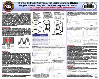
10 likes | 143 Vues
Thermal-hydraulic Analysis of the Series Connected Hybrid Magnet Outsert Using the Computer Program “FLOWER”. Julia C. Luongo 1 , Iain R. Dixon 2 , Andrew V. Gavrilin 2 , and Kurt Cantrell 2 1 Department of Engineering, Swarthmore College, Swarthmore, PA, USA

E N D
Thermal-hydraulic Analysis of the Series Connected Hybrid Magnet Outsert Using the Computer Program “FLOWER” Julia C. Luongo1, Iain R. Dixon2, Andrew V. Gavrilin2, and Kurt Cantrell2 1 Department of Engineering, Swarthmore College, Swarthmore, PA, USA 2 Magnet Science & Technology, National High Magnetic Field Laboratory, Tallahassee, FL, USA 3 Pipe System Since the field gets weaker as the windings are further from the center of the magnet, the pump model was split into 3 pipes representing the 21 layers for more accurate heating profile. ABSTRACT The Series Connected Hybrid consists of a resistive insert inside a superconducting outsert. The outsert is wound with Nb3Sn/Cu inside a stainless steel jacket in what is termed a cable-in-conduit conductor (CICC). Supercritical helium at 4.5 K flows inside the CICC. The outsert coil is composed of 21 winding layers which, for helium flow purposes, are connected in parallel. The objective of this work was to use the computer program FLOWER to model the helium flow in the outsert magnet and determine flow patterns under normal operating conditions. It was shown that using a closed circuit pump model was more effective than using differential pressure to drive the flow. The results show that for the expected heat input due to AC losses, even though there is strong backflow in some of the layers, the operating temperature remains within safe limits. INTRODUCTION A hybrid magnet being developed at the NHMFL consists of a Florida-Bitter resistive magnet nested within a superconducting outer magnet constructed with a cable-in-conduit conductor (CICC). The CICC uses a cable of multifilamentary Nb3Sn/Cu strands inside a jacket that confines flowing supercritical helium in direct contact with the cable strands and jacket. Helium flow through the CICC outsert coil is split into parallel paths. The objective of this work is to model the flow in the 21 parallel paths represented by each layer of CICC in the outsert. APPROACH The FLOWER code FLOWER is a computer code for the thermo-hydraulic simulation of an arbitrary, user-defined assembly of manifolds, pipes, heat exchangers, valves, turbines and pumps, the hydraulic network. It provides pressure, temperature and mass flow conditions throughout the network as a function of time. It is aimed at the simulation of the integrated response of a fluid network, including the pipework of a magnet/refrigerator system [1]. As part of this project, a dedicated computer was converted to run Linux under VMware so that the program FLOWER would run under Linux while all other input/output operations could be accomplished on the host operating system (Windows). VMware software allows a user to virtually partition the hard drive so that both the guest and host operating systems can run at the same time. [3] Flow Model of the Series-Connected Hybrid Magnet Two different scenarios were tested and compared to determine which is the more accurate model. In order to dramatically decrease program running time, the 21 winding layers were superimposed into one pipe representing 21 layers. A third system lumping the 21 layers into 3 parallel paths also was developed after comparing the two initial cases. RESULTS The heating table and plot show the assumed heating schedule (80 second flat pulse) and its intensity for the different scenarios. Pump 21 layers of parallel flow windings superimposed into one pipe. Closed circuit with a pump in order to enforce a given mass flow. 3 Pipe System- For more accurate heating, the 21 layers (previously represented by a single pipe) are represented by 3 parallel paths: high, medium, and low field layers. The first 9 layers are exposed to high field, the next 7 to medium field, and the last 4 layers to low field. Differential Pressure Same case as the pump model except that the flow is pressure-driven. A drop in pressure between the inlet and outlet causes flow through the pipe. • CONCLUSIONS • Two modeling approaches were used in FLOWER: pump and differential pressure. The pump model proved to be a more realistic way of modeling helium flow through the CICC outsert coil. • The advantage of the pump model is its ability to set a constant mass flow, which is not possible in the pressure differential model. • The pump model is a closed circuit system, which more accurately depicts the cryogenic system of the SCH. • With the realistic heating inputs and mass flow rate used, temperatures in the magnet did not exceed the operating limit. According to these models, the magnet would operate successfully. • Flow is restricted by the length of the layers and the temperature of the helium. For the 3 Pipe System, length dominates because little backflow is shown to occur for the high field layer. Helium wants to flow through the higher field regions, which is what we want to happen. • The 3 Pipe System yielded more realistic results, the next step should be modeling the system with 21 different heat inputs (21 parallel pipes for the 21 winding layers). • Since flow models will only increase in complexity, using a higher performance computer is advised in order to dramatically decrease the run-time of a simulation. • REFERENCES • CryoSoft FLOWER User’s Guide, Version 4.0, October 2002. • Van Sciver, Steven W., Helium Cryogenics, The International Cryogenics Monograph Series, 384-387, 1986. • VMware Workstation 4 User’s Manual, 65-116, 2004. • H. Katheder, “A general formula for calculation of the friction factor for cable-in-conduit conductors,” The NET Team Internal Note N/R.0821/26/A. • Acknowledgements • I would like to thank everyone that made this project possible: Andy Gavrilin and Kurt Cantrell for all of their help, and, in particular, my mentor Iain Dixon for his help, guidance and patience. I would also like to thank Jack Toth for his great help with all of my Linux and • VMware questions. In addition, many thanks to the entire CIRL group, the NHMFL, • and the NSF for making this program available and allowing me to participate. Highest temperature is 5.54 K, occurring at the peak of heating (80 s). Cooling occurred first in the high field layers, showing that the warm helium slug moves fastest through high field layers. Velocity profile for the high field layer. Most helium flow occurs in this layer with a small section showing backflow. Highest flow velocity is reached in this layer. Heating Characteristic Velocity profile for low field layer. Helium is almost symmetrically expelled in both directions. Velocities are much lower, most likely due to the low levels of heating in this region along with longer coil length caused by the fact that the windings are further from the center of the magnet. Velocity profile for medium field layer. More backflow occurs in this layer but velocities are only slightly lower than in high field layers. Pump Model- Volumetric pump allows for a user-defined constant mass flow. This creates a more realistic model because the pump adjusts the pressure drop in order to achieve the desired massflow (same as the magnet would operate). [2] Schematic of helium flow paths of the outsert coil winding Cross-section of the Series Connected Hybrid Velocity profile within the outsert winding after one cycle. Heating causes helium to expand and expel in both directions. Negative velocities indicate backflow. Temperature profile within the outsert winding after one cycle. Shows a cooling wave propagation as warm helium is replaced by cold helium. Differential Pressure Model- Adjust inlet and outlet volume pressure to force a specific mass flow. Temperature profile shows that the maximum temperature within the outsert winding is higher in this model using the same amount of heating. Cooling also occurred more slowly. Velocity profile shows that no backflow occurred early in the cycle but more backflow occurred later in the heating cycle.


