Download
1 / 32
580 likes | 1.4k Vues
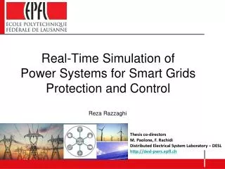
Real-Time Simulation of Power Systems for Smart Grids Protection and Control . Reza Razzaghi. Thesis co-directors M. Paolone , F. Rachidi Distributed Electrical System Laboratory – DESL http ://desl- pwrs.epfl.ch. Introduction Motivation State-of-the-art

E N D
Real-Time Simulation of Power Systems for Smart Grids Protection and Control Reza Razzaghi Thesis co-directors M. Paolone, F. Rachidi Distributed Electrical System Laboratory – DESL http://desl-pwrs.epfl.ch
Introduction Motivation State-of-the-art FPGA-based real-time simulator for power systems Optimal selection of switch parameter FPGA-based real-time simulator Fault location in transmission lines using EMTR Time reversal process Experimental validation Simulation case studies Outline 1
Introduction Motivation State-of-the-art FPGA-based real-time simulator for power systems Optimal selection of switch parameter FPGA-based real-time simulator Fault location in transmission lines using EMTR Time reversal process Experimental validation Simulation case studies Outline 2
IntroductionMotivation • Smart Grids • Progressiveinstallationof distributed energy resources (DERs) • Evolution of distribution networks passive active • Planning • Operation • Control • Challenges • Distribution network protection and fault location • Optimal voltage and power flow controls Real-time monitoring and control functionalities 3
Introduction State-of-the-Art • Existing real-time simulators are based on various types of processors: • General purpose processors (GPPS) • Digital signal processors (DSPs) • Computer clusters • However, existing real-time simulators have limitations such as: • Lower-bound limitation of the minimum simulation time-step • Limitation in simulation of high frequency phenomena (power converters, short transmission lines) • Inherent complexity of the hardware architecture characterized by several layers each one devoted to a specific function (i.e. A/D and D/A conversions, CPU computation, data transfer and storage, etc.). FPGA-based real-time simulators 5
Introduction State-of-the-Art • FPGA-based real-time simulator • FPGA-based real-time simulator for electromagnetic transients study of power electronics [5] • FPGA-based real-time simulator for electromagnetic transients study of AC machines [17] • FPGA-based real-time simulator for electromagnetic transients studies of power systems including transmission lines [7] • Fixed Admittance Matrix • Nodal Method (FAMNM) • Classical nodal analysis • Lumped elements • Transmission lines model • Classical nodal analysis • Not-fixed admittance matrix 7
Introduction Motivation State-of-the-art FPGA-based real-time simulator for power systems Optimal selection of switch parameter FPGA-based real-time simulator Fault location in transmission lines using EMTR Time reversal process Experimental validation Simulation case studies Outline 8
FPGA-based real-time simulator for power systems • 1- Network solution method • Modified nodal analysis (MNA) • State-space method • 2- Numerical integration method • Trapezoidal method • Euler methods • 3- Network components model • Lumped elements (R,L,C,…) • Transmission lines 9
FPGA-based real-time simulator for power systems • Methodology • Modified nodal analysis (MNA) 10
FPGA-based real-time simulator for power systems • Methodology • Fixed Admittance Matrix Nodal Method (FAMNM) system nodal matrix remains unchanged during switching transitions Pejovic, P.; Maksimovic, D, “A Method for Fast Time-Domain Simulation of Networks with Switches,” IEEE Trans. Power Electron. 1994, 9, 449–456. 11
FPGA-based real-time simulator for power systems • Optimal selection of discrete-time switch model 12
FPGA-based real-time simulator for power systems • Optimal selection of discrete-time switch model Objective function Error function Losses function 13
FPGA-based real-time simulator for power systems • Optimal selection of discrete-time switch model 14
FPGA-based real-time simulator for power systems • Optimal selection of discrete-time switch model 15
FPGA-based real-time simulator for power systems • System configuration 16
FPGA-based real-time simulator for power systems • Proposed algorithm for FPGA-based real-time simulator 17
FPGA-based real-time simulator for power systems • Application example Simulation time step: 4ms 18
FPGA-based real-time simulator for power systems • Application of the FPGA-based real-time simulator joined with the EMTR Fault Location 19
Introduction Motivation State-of-the-art FPGA-based real-time simulator for power systems Optimal selection of switch parameter FPGA-based real-time simulator Fault location in transmission lines using EMTR Time reversal process Experimental validation Simulation case studies Outline 20
FPGA-based real-time simulator for power systems • Fault location in power systems transmission lines • Transmission system: Power system security • Distribution system: Power system quality i) Analysis of pre- and post-fault voltage/current phasors Fault location methods: ii) Analysis of fault-originated electromagnetic transients of currents and/or voltages Active distribution networks: Electromagnetic Time Reversal 21
Fault location in transmission lines using EMTR • The time-reversal focusing procedure: a. Transient waveforms generated by a source propagate through the medium and are recorded by sensors. b. The recorded signals are reversed in time and re-emitted back to the medium. In view of the reversibility in time of the wave equation, travelling waves are refocused into the source point • N. Mora, F. Rachidi, M. Rubinstein, "Application of the Time Reversal of Electromagnetic Fields to Locate Lightning Discharges", Journal of Atmospheric Research, Vol. 117, pp. 78-85, 2012. 22
Fault location in transmission lines using EMTR • The time-reversal focusing procedure: 23
Fault location in transmission lines using EMTR • Electromagnetic time reversal (EMTR) in transmission lines Wave equation is time invariant 24
Fault location in transmission lines using EMTR • Fault location algorithm • based on EMTR 25
Fault location in transmission lines using EMTR • Application example HV transmission lines (simulation) 26
Fault location in transmission lines using EMTR • Application example (reduced-scale experimental setup) 27
Fault location in transmission lines using EMTR Inhomogeneous network composed of mixed overhead-coaxial cable lines. 3ph fault, Xf= 7km, Rf= 0 Ω 3ph fault, Xf=5 km, Rf= 100 Ω 28
Fault location in transmission lines using EMTR • B. Radial distribution network: IEEE 34-bus test distribution feeder 3ph, Xf= 808, Rf=0 Ω 3ph, Xf= 812, Rf=100 Ω 29
Fault location in transmission lines using EMTR • B. Radial distribution network: IEEE 34-bus test distribution feeder 1ph, Xf= 810, Rf=0 Ω 1ph, Xf= 806, Rf=100 Ω 30
Fault location in transmission lines using EMTR • C. Series-compensated transmission line Single-phase-to-ground fault Double-phase-to-ground fault Three-phase-to-ground fault 31
Thanks for your attention Questions?