Download
1 / 34
690 likes | 1.81k Vues
Electronic Devices Ninth Edition Floyd. Chapter 11. Summary. Thyristors.

E N D
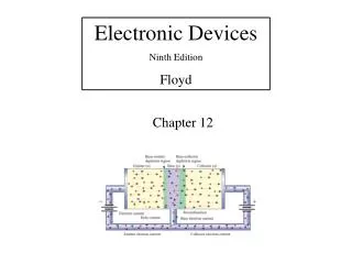
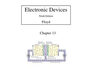
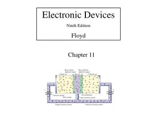
Electronic Devices Ninth Edition Floyd Chapter 11
Summary Thyristors Thyristors are a class of semiconductor devices characterized by 4-layers of alternating p- and n-material. Four-layer devices act as either open or closed switches; for this reason, they are most frequently used in control applications. Some thyristors and their symbols are
Summary Thyristors The concept of 4-layer devices is usually shown as an equivalent circuit of a pnp and an npn transistor. Ideally, these devices would not conduct, but when forward biased, if there is sufficient leakage current in the upper pnp device, it can act as base current to the lower npn device causing it to conduct and bringing both transistors into saturation.
Summary The Four-Layer Diode The 4-layer diode (or Shockley diode) is a type of thyristor that acts something like an ordinary diode but conducts in the forward direction only after a certain anode to cathode voltage called the forward-breakover voltage is reached. The 4-layer diode has two leads, labeled the anode (A) and the cathode (K). The symbol reminds you that it acts like a diode. It does not conduct when it is reverse-biased.
Summary The Four-Layer Diode The characteristic curve for a 4-layer diode shows the forward blocking region. When the anode-to-cathode voltage exceeds VBR, conduction occurs. The switching current at this point is IS. Once conduction begins, it will continue until anode current is reduced to less than the holding current (IH). This is the only way to stop conduction.
Summary The SCR The SCR had its roots in the 4-layer diode. By adding a gate connection, the SCR could be triggered into conduction. This improvement made a much more useful device than the 4-layer diode. The SCR can be turned on by exceeding the forward breakover voltage or by gate current. Notice that the gate current controls the amount of forward breakover voltage required for turning it on.
Summary The SCR Like the 4-layer diode, the SCR will conduct as long as forward current exceeds IH. There are two ways to drop the SCR out of conduction: 1) anode current interruption and 2) forced commutation. Anode current can be interrupted by breaking the anode current path (shown here), providing a path around the SCR, or dropping the anode voltage to the point that IA < IH. Force commutation uses an external circuit to momentarily force current in the opposite direction to forward conduction. SCRs are commonly used in ac circuits, which forces the SCR out of conduction when the ac reverses.
Summary SCR Specifications Three important SCR specifications are: Forward-breakover voltage, VBR(F): This is the voltage at which the SCR enters the forward-conduction region. Characteristic for IG = 0 Holding current, IH: This is the value of anode current below which the SCR switches from the forward-conduction region to the forward-blocking region. Gate trigger current, IGT: This is the value of gate current necessary to switch the SCR from the forward-blocking region to the forward-conduction region under specified conditions.
Summary SCR Applications SCRs are used in a variety of power control applications. One of the most common applications is to use it in ac circuits to control a dc motor or appliance because the SCR can both rectify and control. The SCR is triggered on the positive cycle and turns off on the negative cycle.A circuit like this is useful for speed control for fans or power tools and other related applications.
Summary SCR Applications Another application for SCRs is in crowbar circuits (which get their name from the idea of putting a crowbar across a voltage source and shorting it out!) The purpose of a crowbar circuit is to shut down a power supply in case of over-voltage. Once triggered, the SCR latches on. The SCR can handle a large current, which causes the fuse (or circuit breaker) to open.
Summary The Diac The diac is a thyristor that acts like two back-to-back 4-layer diodes. It can conduct current in either direction. Because it is bidirectional, the terminals are equivalent and labeled A1 and A2. The diac conducts current after the breakdown voltage is reached. At that point, the diac goes into avalanche conduction, creating a current pulse sufficient to trigger another thyristor (an SCR or triac). The diac remains in conduction as long as the current is above the holding current, IH.
Summary The Triac The triac is essentially a bidirectional SCR but the anodes are not interchangeable. Triggering is done by applying a current pulse to the gate; breakover triggering is not normally used. When the voltage on the A1 terminal is positive with respect to A2, a gate current pulse will cause the left SCR to conduct. When the anode voltages are reversed, the gate current pulse will cause the right SCR to conduct.
Summary Triac Applications Triacs are used for control of ac in applications like electric range heating controls, light dimmers, and small motors. Like the SCR, the triac latches after triggering and turns off when the current is below the IH, which happens at the end of each alteration.
Summary The Silicon-Controlled Switch (SCS) The SCS is similar to an SCR but with two gates. It can be triggered on with a positive pulse on the cathode gate, and can be triggered off with a positive pulse on the anode gate. In this example, the SCS is controlling a dc source. The load is in the cathode circuit, which has the advantage of one side of the load being on circuit ground.
Summary The Unijunction Transistor (UJT) The UJT consists of a a block of lightly-doped (high resistance) n-material with a p-material grown into its side. It is often used as a trigger device for SCRs and triacs. The UJT is a switching device; it is not an amplifier. When the emitter voltage reaches VP (the peak point), the UJT “fires”, going through the unstable negative resistance region to produce a fast current pulse.
Summary The Unijunction Transistor (UJT) The equivalent circuit for a UJT shows that looks like a diode connected to a voltage divider. The resistance of the lower divider (r’B1) is inversely proportional to the emitter current. When the pn junction is first forward-biased, the junction resistance of r’B1 suddenly appears to drop, and a rush of current occurs. An important parameter is h, which is the intrinsic standoff ratio. It represents the ratio of r’B1 to the interbase resistance r’BB with no current.
Summary The Unijunction Transistor (UJT) Application A circuit using a UJT to fire an SCR is shown. When the UJT fires, a pulse of current is delivered to the gate of the SCR. The setting of R1 determines when the UJT fires. The diode isolates the UJT from the negative part of the ac. The UJT produces a fast, reliable current pulse to the SCR, so that it tends to fire in the same place every cycle.
Summary The Programmable Unijunction Transistor (PUT) The PUT is a 4-layer thyristor with a gate. It is primarily used as a sensitive switching device. The gate pulse can trigger a sharp increase in current at the output. The characteristic of a PUT is similar to a UJT, but the PUT intrinsic standoff ratio can be “programmed” with external resistors and the UJT has a fixed ratio.
Summary The Programmable Unijunction Transistor (PUT) The principle application for a PUT is for driving SCRs and triacs, but, like the UJT, can be used in relaxation oscillators. For the circuit to oscillate, R1 must be large enough to limit current to less than the valley current (IV). The period of the oscillations is given by: where
Summary The Programmable Unijunction Transistor (PUT) Example: What is intrinsic standoff ratio, and the period of the circuit? Solution: 0.33 0.89 ms Follow-up: What is the frequency? 1.12 kHz
Selected Key Terms The type of 2-terminal thyristor that conducts current when the anode-to-cathode voltage reaches a specified “breakover” value. 4-layer diode Thyristor SCR A class of four-layer (pnpn) semiconductor devices. Silicon-controlled rectifier; a type of three terminal thyristor that conducts current when triggered by a voltage at the single gate terminal and remains on until anode current falls below a specified value.
Selected Key Terms Light-activated silicon-controlled rectifier; a four layer semiconductor device (thyristor) that conducts current in one direction when activated by a sufficient amount of light and continues to conduct until the current falls below a specified value. LASCR Diac Triac A two-terminal four-layer semiconductor device (thyristor) that can conduct current in either direction when properly activated. A three-terminal thyristor that can conduct current in either direction when properly activated.
Selected Key Terms Silicon-controlled switch; a type of four-terminal thyristor that has two gate terminals that are used to trigger the device on and off. SCS UJT PUT Unijunction transistor; a three terminal single pn junction device that exhibits a negative resistance characteristic. Programmable unijunction transistor; a type of three terminal thyristor (physically more like an SCR than a unijunction) that is triggered into conduction when the voltage at the anode exceeds the voltage at the gate.
Quiz 1. The 4-layer (Shockley) diode can conduct current if a. the anode-to-cathode voltage exceeds VBR b. a current pulse is applied to the gate c. both a and b are correct d. none of the above
Quiz 2. The SCR can conduct current if a. the anode-to-cathode voltage exceeds VBR b. a current pulse is applied to the gate c. both a and b are correct d. none of the above
Quiz 3. A bidirectional thyristor is the a. 4-layer diode b. SCR c. triac d. silicon-controlled switch
Quiz 4. A thyristor that looks like two back-to-back 4-layer diodes is the a. SCR b. triac c. SCS d. diac
Quiz 5. An SCR turns off when the a. gate trigger current drops below a specified level b. anode current drops below the holding current c. both a and b are true d. none of the above
Quiz 6. The purpose of a crowbar circuit is to protect a load from a. excessive ripple b. low-voltage c. over-voltage d. all of the above
Quiz 7. A diac and triac are similar in that both devices a. can use breakover triggering b. can be used in ac circuits c. are bidirectional d. all of the above
Quiz 8. A device that has an unstable negative resistance region is the a. UJT b. diac c. triac d. SCS
Quiz 9. The symbol for a silicon-controlled switch (SCS) is (a) (b) (c) (d)
Quiz 10. A programmable unijunction transistor (PUT) is “programmed” by choosing the a. RC time constant b. gate resistors c. power supply voltage d. cathode resistor
Quiz Answers: 1. a 2. c 3. c 4. d 5. b 6. c 7. d 8. a 9. d 10. b