Comparison of Dispersion Effects on Single-Mode Fiber and Optical Amplifier Characteristics
430 likes | 577 Vues
This article discusses the dispersion characteristics in single-mode fibers using a laser with a spectral width of 6 nm over 10 km, calculating how it impacts system performance at different data rates. It also explores optical amplifiers, defining their operation, types, and gain characteristics. Special attention is given to Erbium Doped Fiber Amplifiers (EDFAs) and how to achieve a flat gain curve through various techniques, including co-doping, amplifier length considerations, and optimizing pump wavelengths.

Comparison of Dispersion Effects on Single-Mode Fiber and Optical Amplifier Characteristics
E N D
Presentation Transcript
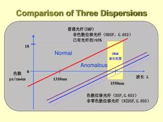
Comparison of Three Dispersions Normal Anomalous
Calculating Dispersion • In a typical single-mode fibre using a laser with a spectral width of 6 nm over a distance of 10 km : Dispersion = 17ps/nm/km × 6 nm × 10 km = 1020 ps • At 1 Gbps a pulse is 1 ns long. So the system would not work. (20% is a good guideline for the acceptable limit.) But it would probably work quite well at a data rate of 155 Mbps (a pulse length of 6.5 ns). • A narrow spectral width laser might produce only one line with a linewidth of 300 MHz. Modulating it at 1 Gbps will add 2 GHz. 2,300 MHz is just less than .02 nm (at 1500 nm). So now: Dispersion = 17ps/nm/km × .02 nm × 10 km = 3.4 ps • In this case, dispersion just ceased to be a problem.
What is an Optical Amplifier • An optical amplifier is a device which amplifies the optical signal directly without ever changing it to electricity. The light itself is amplified.
Principle Pumping Energy Signal in Signal out
How to make an OA • Amplifiers can be built in semiconductor: Semiconductor Optical Amplifiers (SOAs). • Almost any semiconductor laser can be made into an amplifier with a few modifications - • Amplifiers can be built in fibres: Fibre Amplifiers • EDFA: Erbium Doped Fibre Amplifiers • PDFA: Praseodymium Doped Fibre Amplifiers • NDFA: Neodymimum Doped Fibre Amplifiers • SRFA: Stimulated Raman Fibre Amplifiers • PFA: Plastic Fibre Amplifier
Development of OA 光 Low loss window 纤 衰 减 光 增益窗口 增益窗口 波长 PDFA EDFA PDFA EDFA 放 30nm ~ 60nm 30nm ~ 60nm 大 器 SOA SOA 增 益 SRA SRA 1550 nm 850 1310
Technical Characteristics of EDFAs • Efficient pumping • Minimal polarisation sensitivity • Low insertion loss • High output power (this is not gain but raw amount of possible output power) • Low noise • Very high sensitivity • Low distortion and minimal interchannel crosstalk
Definitions • Gain (amplifier) : the ratio in decibels of input power to output power. (dB) • Gain Coefficient: the small signal gain divided by the pump power. (dB/mW) • Bandwidth: the range of wavelengths over which the amplifier will operate.(nm)
Definitions • Gain Saturation: the point where an increase in input power ceases to result in an increase in output power. (dBm) • Polarisation Sensitivity: the difference in gain of an input signal in one polarisation to the gain in the orthogonal polarisation. (typical .01 ~ .1 dB). • Noise Figure: the ratio of the SNR at the input to the SNR at the output (dB).
Flattening the Gain Curve • Operating the device at 77oK. • Introducing other dopant materials (such as aluminium or ytterbium) along with the erbium into the fibre core. • Amplifier length is another factor influencing the flatness of the gain curve. • Controlling the pump power (through a feedback loop) is routine to reduce ASE.
Flattening the Gain Curve • Adding an extra WDM channel locally at the amplifier. This is called “gain clamping”. • Manipulating the shape of the fibre waveguide within the amplifier. Fibres with dual cores have recently been shown to produce much superior gain flatness characteristics.
Flattening the Gain Curve • Using “blazed” fibre Bragg gratings as filters to reduce the peaks in the response curve. In other words, reduce the response at all wavelengths to that of the worst wavelength. This approach has been reported to work well in field trials. • Using channel preemphasis on the signals as they are transmitted. That is,transmit different WDM channels at different power levels to compensate for later amplifier gain characteristics.
Coupler Coupler Filter Gain Clamping EDFA EDFA
Gain locker EDF Pin Pout Power Controller Detecting Pin Detecting Pout Pump laser
Wideband EDFAs • usual gain window (S- & C-band) • 1525 - 1565 nm • Second gain window (L-band) • 1570 - 1610 nm • Using co-dopants, principally aluminium and phosphorus • Wideband EDFAs • 80 nm.
Co-Dopants • Common co-dopants used are aluminium (Al), ytterbium (Yb) and germanium (Ge). • Ge co-doping produces 1536 nm and 1550 nm gain peaks. • Al broadens and flattens the gain spectrum in the region 1540 nm to1560 nm.
Design of Amplifier Length • Both the signal power level and the pump power level vary along the length of the amplifier: signal travels stronger; pump power level decreases. • Single wavelength operation: Lopt=f(Psig,Ppump,Ce,G) • WDM operation: the flatness of the gain. • The gain spectrum at any point along the amplifier will be different from the spectrum at any other point along the amplifier.
Select Pump Wavelengths • 980 nm is almost twice as efficient, as a pump wavelength, than 1480 nm. • 1480 is within the gain spectrum • 1480 is a two-level laser system • 1480 is temperature-sensitive • disadvantage of 980 nm: quite narrow pump bandwidth
Warning • Pumps need to produce an output of up to 250 mW. • Unless the laser is very carefully designed to protect it you can burn the end facet and erode the LD.
Cladding Pumps Output powers of up to 10 watts!
MultiStage EDFAs 1) To increase the power output whilst retaining low noise 2) To flatten the total amplifier gain response 3) To reduce ASE noise
Remote Pumping • Two fibres are used in the connection - one for the • signal and one for the pump. • to pump at 1480 nm • In a typical undersea system to extend the distance • from around 100 km to 150 or even 200 km.
EDFA System Resilience • Signal passes through the failed amplifier relatively unchanged!
Using OTDRs in Amplified Links • OTDR: optical time-domaim reflector • To diagnose link condition right through the amplifier.
Amplifier Applications • Preamplifiers • Power Amplifiers • Line Amplifiers
Second-Generation EDFAs • An amplifier with any of the following characteristics is “second-generation”: • Multi-stage designs • Use of co-dopants such as ytterbium • Use of multiple pumps • Use of gain-equalisation techniques
Summary of EDFA Characteristics • It is significantly simpler than a repeater and will have a much longer mean time to failure. • It is significantly lower in cost than a repeater. • It will operate at almost any speed. • It can be made physically small enough to fit on a printed circuit card.
Summary of EDFA Characteristics • It will produce a gain in optical signal of about 25 dB. Some amplifiers can produce a gain of 50 dB or even higher. • It will amplify many different wavelengths simultaneously (with some small limitations).
Summary of EDFA Characteristics • Both amplitude (pulse) modulated and coherent (frequency modulated) light as well as cable TV signal could be amplified without distortion. • There is effectively no delay in the amplifier. • It is possible to do end-to-end diagnosis of link faults right through an EDFA. • Amplifiers (like their electrical counterparts) can saturate.
Summary of EDFA Characteristics • There are of course some limitations: • The amplifier itself adds some noise. • Wavelength range limitation • The gain spectrum is not perfectly flat. • Amplifiers do not re-create pulses. • amplifiers must be placed closer together (30 kilometres) than repeaters (50 kilometres) • Transmission at 2.4 Gbps over a distance of 21 000 kilometres was reported
Praseodymium (Pr) Doped Fibre Amplifiers • Operate in the 1300 nm band • The gain available in commercial PDFAs is only around 12 dB • Fluorozirconate (ZBLAN) glasses are used instead of silica. • Nd:YLF at 1047 nm pumps are the ones used in commercial PDFAs.
Neodymium (Nd) Doped Fibre Amplifiers • Nd will amplify over the range 1310 to 1360 nm in ZBLAN glass and between 1360 and 1400 nm in silica. • Efficient pump wavelengths are at 795 and 810 nm.