Data Link Control (DLC)
Data Link Control (DLC). Prof. A. Sahoo KReSIT. DLC topics. Sliding Window Mechanism DLC functionality Well known DLC protocols : HDLC, LAPB, SLIP, PPP Davie, Tanenbaum.

Data Link Control (DLC)
E N D
Presentation Transcript
Data Link Control (DLC) Prof. A. Sahoo KReSIT
DLC topics • Sliding Window Mechanism • DLC functionality • Well known DLC protocols : HDLC, LAPB, SLIP, PPP • Davie, Tanenbaum
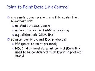
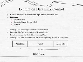
Data Link LayerHow to provide a “reasonable” link abstraction to the higher layers?Reliable communication over a single unreliable physical link.
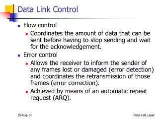
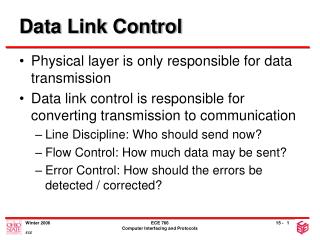
Data Link Layer Requirements Control or Manage the exchange of data between two points. Problems with a communication link: • Frame Synchronization • Flow Control • Error Control • Detection • Correction • Optimal Use of Link
Data link Layer Services to upper layers • Unacknowledged connectionless service • No acks, no connection • Error recovery up to higher layers • For low error-rate links or voice traffic • Acknowledged connectionless service • Acks improve reliability • For unreliable channels. E.g.: Wireless Systems • Acknowledged connection-oriented service • Equivalent of reliable bit-stream • Connection establishment • Packets Delivered In-Order • Connection Release • Inter-Router Traffic • Typically implemented by network adaptor • Adaptor fetches (deposits) frames out of (into) host memory
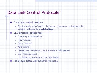
Data link layer functions • Data Link layer functions ( in short) • Provide service interface to the network layer • Framing • Dealing with transmission errors • Regulating data flow • Slow receivers not swamped by fast senders • Addressing • For multi-point links • Link Management ( connection Initiate, Disconnect) • Optimal link uses
DLL HDLC Framing & Synchronization Flow Control Error Control Stop and Wait Sliding Window Bit level Error Detection Frame level Error Correction Stop and Wait ARQ Go Back N ARQ Parity CRC Selective Reject ARQ High level view
Data Transfer • Simple Stop and Wait • Sliding Window (Peterson Davie) Stop and Wait • Send data frame A -->B • B send acknowledgement frame (ACK), B-->A • A waits till ACK comes • On No receipt of ACK, A times-out and resend data frame. • Ensures reliability • Controlled flow • Problems: lower link utilization ( see figure in next slide) • Longer frame to increase link utilization---> not always possible • Buffer overflow • Unavailability of data for bursty traffic • Link capture by one node • Easier error detection, smaller frame transmit on error • So, limit on frame size required, but, • Small frames make Stop & Wait bad for high delay links
Sliding Window • Increased link utilization ( send more number of packets before expecting ack • Reliable transfer ( ack-ed reception) • Flow control • For ordered packet sequence, receiver needs to have some buffer to hold received packets in unordered manner • Flow control: controlled by receiver buffer size • Error detection Sliding Window: • Allow multiple frames to be in transit • Receiver has buffer W long • Transmitter can send up to W frames without ACK • Each frame is numbered ( sequence number) • ACK includes number of next frame expected
Sliding window Sender Sender maintains following three variable • Send window size ( SWS) • Upper bound on number of unacknowledged frame • Last Frame acknowledged • Sequence number of last frame acknowledged • Last Frame sent ( LFS) • Sequence number of last frame sent • Maintain invariant: LFS - LAR <= SWS • When ACK arrives, advance LAR ( by above invariant), thereby opening window • Buffer up to SWS frames
Sliding window Receiver Receiver maintains following three variable • Receive window size ( RWS) • Upper bound on number of out-of-order frames that the receiver is willing to accept (buffer limitation) • Largest acceptable frame (LAR) • Sequence number of largest acceptable frame • Last Frame Received ( LFR) • Sequence number of last frame received • Maintain Invariant: LAF - LFR <= RWS • Frame SeqNum arrives: • if SeqNum <= LFR or SeqNum > LAF, then the frame is outside the receiver window, hence reject. • if LFR < SeqNum <= LAF, then the frame is within the receiver window, hence accept.
Sliding window Receiver • Send Cumulative ACK. • Ack contain the next sequence no n (NFE) expected. • This means till (n-1) no (LFR) is correctly received • Window is adjusted by LAF = LAR + RWS
SWS, RWS and Maximum Sequence Number • Setting SWS and RWS • SWS :- should be guided by BW * delay product • RWS :- • 1 --> no buffering, no ordering ( assuming receiver processor is much faster) • RWS = SWS ---> can order all data sent in one shot by sender • Sequence Number • In previous 2 slides, sequence number assumed to be infinite (not possible) • Has to be finite ( 3 bits in HDLC) • What is the relationship between SWS, RWS and maximum sequence number (MaxSeqNo)? • Rule: received frame numbers and expected frame numbers should be “mutually exclusive” • So what should be relationship between MaxSeqNo, SWS and RWS?
Sequence Number • Example: (MaxSeqNo =7, SWS= RWS =8) • Frames sent 0 to 7 • Frames received 0 to 6. Receiver expecting 7, 0, 1, 2, 3, 4,5 , 6 ( 0-6 next cycle) • Cumulative Ack sent for 6, but Ack is lost on the way • Sender resends 0 to 7 • Receiver accepts all frames, thinking they are from next cycle. • This is a wrong reception, generating duplicate packets to upper layers
Error Control • When a sequence of frames/packets are transmitted over a lossy link the reception faces problems of frame damage, loss, reordering, duplication,insertion • Error Detection • Using acknowledgements • Positive if good frame • Negative if bad frame detected using error detecting codes • Using timers • For lost frames
Error Control • Error Recovery • Re-transmission • ARQ ( Automatic Repeat Request) primarily based on sliding window mechanism • Stop and wait • Go back N • Selective reject (selective retransmission) [Forward Error Correction ( FEC): Use of Redundancy for packet level error correction ( known as Erasure codes) See Keshav, Error control chapter]
Stop and Wait • Source transmits single frame • Wait for ACK • If received frame damaged, discard it • Transmitter has timeout • If no ACK within timeout, retransmit • If ACK damaged,transmitter will not recognize it • Transmitter will retransmit • Receive gets two copies of frame • Use ACK0 and ACK1
Go Back N • Based on sliding window • If no error, ACK as usual with next frame expected • Use window to control number of outstanding frames • If error, reply with rejection • Discard that frame and all future frames until error frame received correctly • Transmitter must go back and retransmit that frame and all subsequent frames
Go Back N • Damaged Frame • Receiver detects error in frame i • Receiver sends rejection-i • Transmitter gets rejection-i • Transmitter retransmits frame i and all subsequent • Lost Frame • Frame i lost • Transmitter sends i+1 • Receiver gets frame i+1 out of sequence • Receiver send reject i • Transmitter goes back to frame i and retransmits
Go Back N • Lost Frame • Frame i lost and no additional frame sent • Receiver gets nothing and returns neither acknowledgement nor rejection • Transmitter times out and sends acknowledgement frame with P bit set to 1 • Receiver interprets this as command which it acknowledges with the number of the next frame it expects (frame i ) • Transmitter then retransmits frame i
Go Back N • Damaged Acknowledgement • Receiver gets frame i and send acknowledgement (i+1) which is lost • Acknowledgements are cumulative, so next acknowledgement (i+n) may arrive before transmitter times out on frame i • If transmitter times out, it sends acknowledgement with P bit set as before • This can be repeated a number of times before a reset procedure is initiated • Damaged Rejection • As for lost frame
Selective Reject • Also called selective retransmission • Only rejected frames are retransmitted • Subsequent frames are accepted by the receiver and buffered • Minimizes retransmission • Receiver must maintain large enough buffer • More complex logic in transmitter
High Level Data Link Control • Derived from SDLC (synchronous DLC) developed by IBM in the 1970s • SDLC modified by ISO became HDLC • Basis for some protocols that are used widely • LAP-B in X.25 networks (the “original” packet switched network) • Defined for both point-to-point and multi-drop lines
HDLC Station Types • Primary station • Controls operation of link • Frames issued are called commands • Maintains separate logical link to each secondary station • Secondary station • Under control of primary station • Frames issued called responses Design takes care of one host computer and many terminal configuration • Combined station • May issue commands and responses
HDLC Link Configurations • Unbalanced • One primary and one or more secondary stations • Supports full duplex and half duplex • Balanced • Two combined stations • Supports full duplex and half duplex
HDLC Transfer Modes Two widely used mode: • Normal Response Mode (NRM) • Unbalanced configuration • Primary initiates transfer to secondary • Secondary may only transmit data in response to command from primary • Used on multi-drop lines • Host computer as primary • Terminals as secondary • Asynchronous Balanced Mode (ABM) • Balanced configuration • Either station may initiate transmission without receiving permission • Most widely used • No polling overhead
HDLC Transfer Modes • Asynchronous Response Mode (ARM) • Unbalanced configuration • Secondary may initiate transmission without permission form primary • Primary responsible for line • rarely used
Frame Structure • All transmissions in frames • Single frame format for all data and control exchanges • Flag field : used for framing, use of bit stuffing technique • 8 bit link layer address • Control field: describes various operation modes and packet type. Describes various phase of ARQ system
Control Field • Normally uses Go back N with MaxSeqNo =8 • Different for different frame type. Frame types are: • Information - data to be transmitted to user (next layer up) • Flow and error control piggybacked on information frames • contains the sequence number • Supervisory - ARQ when piggyback not used ( no reverse data packet to send) • Unnumbered - supplementary link control for Initiation and Termination of link • First one or two bits of control field identify frame type
Poll/Final Bit • Use depends on context • Command frame • P bit • 1 to solicit (poll) response from peer • Response frame • F bit • 1 indicates response to soliciting command
HDLC Operation • Exchange of information, supervisory and unnumbered frames • Three phases • Initialization • Data transfer • Disconnect
Other DLC Protocols (LAPB,LAPD) • Link Access Procedure, Balanced (LAPB) • Part of X.25 (ITU-T) • Subset of HDLC - ABM • Point to point link between system and packet switching network node • Link Access Procedure, D-Channel • ISDN (ITU-D) • ABM • Always 7-bit sequence numbers (no 3-bit) • 16 bit address field contains two sub-addresses • One for device and one for user (next layer up)
Other DLC Protocols SLIP & PPP ( Tanenbaum pg 229) • SLIP:- Serial Line IP • No error detection or correction • Works only for IP • Needs fixed IP no ---> DHCP does not work • Not Standardized • No Authentication
PPP Point to Point Protocol • Works for any network layer • IP address can be configured • No error/ flow control • Authentication possible
Other DLC Protocols (Frame Relay) (2) • ABM, 7-bit sequence numbers, 16 bit CRC • Address field (2, 3 or 4 octet) • Data link connection identifier (DLCI) • Identifies logical connection
Other DLC Protocols (ATM) • Asynchronous Transfer Mode • Streamlined capability across high speed networks • Not HDLC based • Frame format called “cell” • Fixed 53 octet (424 bit) • Details later