Download
1 / 32
320 likes | 613 Vues
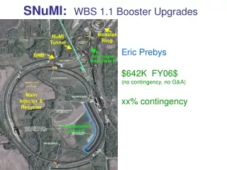
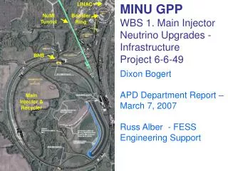
LINAC. NuMI Tunnel. Booster Ring. BNB. MINU GPP WBS 1. Main Injector Neutrino Upgrades - Infrastructure Project 6-6-49. Dixon Bogert APD Department Report – March 7, 2007 Russ Alber - FESS Engineering Support. Main Injector & Recycler. MINU EXECUTIVE SUMMARY FROM CDR and PEP.

E N D
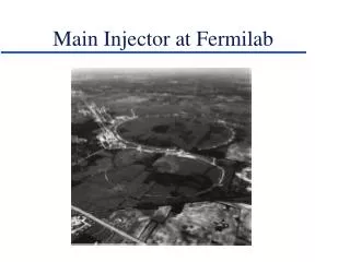
LINAC NuMI Tunnel Booster Ring BNB MINU GPP WBS 1. Main InjectorNeutrino Upgrades - InfrastructureProject 6-6-49 Dixon BogertAPD Department Report – March 7, 2007 Russ Alber - FESSEngineering Support Main Injector & Recycler
MINUEXECUTIVE SUMMARY FROM CDR and PEP The Main Injector Neutrino Upgrade Project (MINU) will provide new service buildings to house new power supplies and new kicker magnet support equipment to support the future increase of the NuMI beam power from 400kW to 700 kW. The use of the accumulator ring for the stacking of protons is made possible as well. The project will require construction of two new service buildings around the Main Injector, MI-14 and MI-39, and one small addition at MI-60 to house an anode power supply. The work would require excavation for installation of penetrations from the new service buildings to the existing Main Injector tunnel, excavation for building foundations at all three locations, utility installation in trenches for power and communication ductbanks, and industrial cooling water (ICW) piping. Floodplain mitigation for the area taken at MI-14 and Space Compensation demolition for the entire area to be constructed is also required.
WBS Description & Scope 1.1 Space Management (Remove 4000sf somewhere) 1.2 MI-14 Service Building (2250sf; also floodplain mitigation) 1.4 MI-60 4th Anode Supply Room (250sf) 1.3 MI-39 Service Building (1500sf)
GPP Project Schedule • Project Definition – Preliminary Discussions with local DOE staff • Submit GPP Documentation – March 2007 • GPP Project Approval – March/April 2007 • Design – FESS and outside AE – Remainder of FY 2007 • Construction Bid and Award – FY 2008 • Construction Start – Before/Start FY 2008 shutdown • Penetrations complete –End of FY 2008 shutdown • All construction complete – Early FY 2009 The shoring to support the Main Injector Precast unit roofs will simultaneously block the aisles to thru transport traffic at MI-14 and MI-39. This will probably last about four weeks, and isolate the “MI-30 Half” of the FMI from the “MI-60 Half” for any delivery or transit.
MI-14 Service Building 1.2 MI-14 Service Building (2250sf; also floodplain mitigation) Service Building housing kicker power supplies for 8 GeV Injection into the Recycler Ring, also power supplies for magnets in the 8 GeV injection line, space for fluorinert skids for cooling the kickers. Penetrations must be constructed for kicker cables, cooling water, and fluorinert lines. Building footprint subtracts from Indian Creek floodplain area; must be mitigated.
MI-14 Service Building Specifications (Selected items from CDR) • One story building with 11.5’ clear height • Depressed floor for 30’x 50’ kicker room to contain oil from equipment to mitigate spills • 30’ x 25’ power supply room • 16 – 6” conduit penetrations from building to MI enclosure for 8 known and 8 future cable runs for kicker room • 6-6” conduit penetrations from building to MI enclosure for power supply room • Straight 6” penetration to MI enclosure for 1.5” LCW supply and return piping, with both pipes in same conduit. • Anticipating heat rejection to LCW is 50 kW • Two 5 inch "straight shot" conduits to the tunnel for installing fluorinert cooling system • Building power: new 750 kVA , 13.8kV – 480/277V beamline power transformer located adjacent to the building. • New 15kV air switch at MI-10 service building, with existing 15kV feeders 96//97 extended from MI-8 • Service Building via existing MI ductbank. New 225A, 480/277V feed from MI-10 Service Building to • power fluorinert pumps (480V), kicker power supplies, electronics racks, and miscellaneous building loads. • Communications/controls to be supplied from MI-10 via new ductbank to MI-14 • ICW supply/return from main distribution along Indian Creek Road to serve for fire suppression • Concrete masonry wall separating power supply and kicker rooms • Two sets of double doors for entrance into kicker room from outside, with a removable panel at the top of the • doors for infrequent loading of tall equipment. Aprons in front of the building should extend 8’ from door. • One overhead and one single mandoor from outside into power supply room • Air conditioning and unit heaters serving each of the 2 rooms • Two 18” cable trays in ceiling of MI enclosure for likely 32 cables to kicker magnets, with maximum 200 ft length • of cable from equipment in building to equipment in tunnel
MI-39 Service Building 1.3 MI-39 Service Building (1500sf) Service Building housing kicker power supplies for Recycler Gap Cleaning Kicker, possibly the Recycler Abort Kicker, and space for fluorinert skids for cooling the kickers. Penetrations must be constructed for kicker cables, cooling water, and fluorinert lines.
MI-39 Service Building Specifications (Selected items from CDR) • One story building with 11.5’ clear height • Depressed floor in 30’ x 50’ building to contain oil from equipment to mitigate spills • 16 – 6” conduit penetrations from building to MI enclosure for 8 known and 8 future • cable runs • Straight 6” penetration to MI enclosure for 1.5” LCW supply and return piping, with • both pipes in same conduit. Anticipating heat rejection to LCW is 50 kW • Two 5 inch "straight shot" conduits to the tunnel for installing fluorinert cooling system • Building power: new 225A, 480/277V feed from MI-40 Service Building to power • fluorinert pumps (480V), kicker power supplies, electronics racks, and • miscellaneous building loads. • Kicker power requirements: Approximately 30 kVA, 208V power with dedicated • 45kVA shielded transformer and panelboard • Electronics racks: Approximately 10 racks with 2-20A, IP, 120V branch circuits to each. • Communications/controls to be supplied from MI-40 via new ductbank to MI-39 • ICW supply/return from main distribution along Indian Creek Road to serve for fire • suppression • Two sets of double doors for entrance from outside, with a removable panel at the top • of the doors for infrequent loading of tall equipment. Aprons in front of the • building should extend 8’ from door. • Air conditioning and unit heating • Two 18” cable trays in ceiling of MI enclosure for likely 32 cables to kicker magnets, • with maximum 200 ft length of cable from equipment in building to equipment in tunnel
MI-60 Anode Supply Room 1.4 MI-60 4th Anode Supply Room (250sf) Six more rf systems; two in the Main Injector and four in the Recycler Ring will be added to the existing 18 systems. This raises the number of rf systems by one third, raising the number of anode supplies from three to four. The functionality of the additional anode supply is identical to the existing three supplies, so the space and enclosure requirements are also identical.
The MINU GPP Civil Construction is relatively straightforward. If funding is provided and approval is given for construction of the penetrations and footings at MI-14 and MI-39 during the summer shutdown of 2008, then the rest of the work as well as the anode supply room can be accomplished independently of the accelerator operating schedule. This would permit the completion of the kicker buildings by early FY09. Summary
SciBooNE Civil Construction SciBooNE Building Construction SciBooNE is an experiment that is moving the “SciBar” Detector from Japan to the United States for a test run before returning it to Japan for installation at JPARC. The detector is now being installed 100 meters downstream of the MiniBooNE Target at MI-12. The excavation for the detector enclosure started in late September, and was completed in early February. The design is shown in the following two slides, and a “fish-eye” view of the completed work follows. SciBooNE
SciBooNE Civil Construction SciBooNE Building Construction Mini BooNE Target SciBooNE Detector 100 meters SciBooNE
SciBooNE Detector SciBooNE Building Construction SciBooNE
SciBooNE Building Completed SciBooNE Building Construction