Download
1 / 27
270 likes | 403 Vues
Coupled Geomechanical-Fluid Flow Modelling for Carbon Capture and Storage CO 2 Injection Scenarios. T. Lynch 1,2 , Q.J. Fisher 2 , D. Angus 2 , P. Lorinczi 2. 1 Low Carbon Technologies Doctoral Training Centre, University of Leeds

E N D
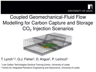
Coupled Geomechanical-Fluid Flow Modelling for Carbon Capture and Storage CO2 Injection Scenarios T. Lynch1,2, Q.J. Fisher2, D. Angus2, P. Lorinczi2 1 Low Carbon Technologies Doctoral Training Centre, University of Leeds 2 Centre for Integrated Petroleum Engineering and Geoscience, University of Leeds
Overview Summary Background – PhD Project and research group Context of research – Aims of research and wider research goals Modelling approach – Coupled geomechanical-fluid flow modelling Modelling capabilities – Current and future capabilities Current work – “Two fault” generic model Current work – Full field modelling
Background PhD Project and Research group Doctoral Training Centre in Low Carbon Technologies – Wide ranging centre for low carbon energy technologies - collaboration between Engineering and Earth Sciences Mainly work with CiPEG – Quentin Fisher and Doug Angus Interdisciplinary PhD – Geological Storage of CO2 in the UK: Risks and Opportunities – mainly technical but also focuses on risk and risk based regulation
Context of research Aims of research and wider research goals • Developed ‘risk register’ of storage risks - as part of lit. review similar to work of others e.g. Quintessa database • Used to identify risks where further research beneficial • Numerical approach applied to: • Stress path hysteresis • Temperature effects in reservoirs
Coupled Modelling Approach How do we model flow and geomechanics? Industry standard – fluid flow model – pressure & saturation
Coupled Modelling Approach How do we model flow and geomechanics? Surface No account of interaction with rock above reservoir
Coupled Modelling Approach How do we model flow and geomechanics? Stresses in material in and around reservoir affect flow
Modelling Capabilities Couple methodology TEMPEST - Initial grid - Initial porosity - Pressures • Modified pore volume ELFENRS ELFEN Couple industry standard software – improve solution
Coupled Modelling Approach Coupled modelling TEMPEST Universities of Leeds and Bristol and Rockfield Software Ltd. developed coupled methodology ELFEN (geomechanics) – Tempest (flow) - Initial grid - Initial porosity - Pressures • Modified pore volume ELFENRS ELFEN
Modelling Capabilities Current capabilities and future developments • SR3 – calibrate with triaxial – large strains, wide range initial stress • Geometry - complex • Uplift and surface deformation • Seismics and Microseismics TEMPEST - Initial grid - Initial porosity - Pressures • Modified pore volume ELFENRS ELFEN • Future: • Temperature – through manual pass through from Tempest, hope to automate
Coupled Modelling Approach Fluid flow modelling Tempest black oil flow simulation – simplification - cut down run times Using experimentally derived relative permeabilities – available for fault and host rock Restart runs allow multiple phases – depletion/injection Message passing interface – allows efficient coupling w/out write files
Current work Generic “Two fault” model • 3km and 2km depth versions • Sandstone reservoir, shale over/sideburden • Fault transmissiblity – sealing and non-sealing • Fault movement also controlled with friction parameter
Current work Stress path hysteresis • Stress path hysteresis • Reduction of fracture pressure on injection • Santarelli, Tronvoll et al 1998 and Santarelli, Havmoller et al 2008 • Need to investigate more parameters • Investigate realistic scenarios • Use realistic well/lab data • Investigate in realistic field
Mohr Circles and Stress Stress path hysteresis a) Classic textbook pore pressure response
Mohr Circles and Stress Stress path hysteresis b)/c) Reservoir scale pore pressure/stress coupling
Mohr Circles and Stress Stress path hysteresis d) Stress path hysteresis e.g Field data from: Santarelli, Tronvoll et al 1998 and Santarelli, Havmoller et al 2008
Current work Stress path hysteresis • Stress path hysteresis • Reduction of fracture pressure on injection • Santarelli, Tronvoll et al 1998 and Santarelli, Havmoller et al 2008 • Need to investigate more parameters • Investigate realistic scenarios • Use realistic well/lab data • Investigate in realistic field
Current work Generic “Two fault” model - Results • Run several cases exploring: • Uncoupled/coupled • Different injection scenarios • Different fault properties • Temperature • Working with DA exploring: • Implemented seismic code to produce synthetic seismic from models
Current Work Full field model • Obtained full field dataset of offshore oil field • History match data • North Sea abandoned field - potential target for EOR/CO2 storage • Currently: • Building geomechanical model – FE mesh • In order to: • Use workflow from two fault model • Investigate stress path hysteresis incl. temp effects
Current Work Full field model • Progress • Constructed horizons for over/side/underburden • Initial work on deriving parameters for geomechanical model • Remaining • Build realistic representation of faults in model – preserve geometry + create watertight intersections • Intersecting mesh with good equilateralarity
Current Work Full field model Fault offset - Discontinuity
Current Work Full field model Intersection of fault/horizon – must be node sharing + watertight
Current Work Full field model To mesh in goCAD must also remove ‘free extremities’
Current Work Full field model To mesh in goCAD must also remove ‘free extremities’
Current Work Full field model
Summary • Developing complex models to investigate CO2 injection scenarios • Potential for investigating multiple aspects of a problem • Including geomechanics, seismics, microseismics • Developing capability to assess some risks that have received little attention in literature so far • Have field data for a specific site in the UK • Ongoing development of workflow to produce realistic field geometries with incorporation of faults – still a difficult and time consuming process