Download
1 / 31
310 likes | 331 Vues
Explore the world of wide-angle vision and synthetic environments in creating digital panoramas and mosaics for enhanced realism. Learn about multi-perspective mosaicing techniques, motion analysis, blending, and layer composition for a comprehensive representation.

E N D
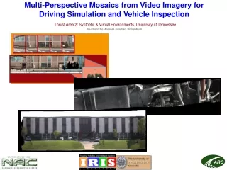
Multi-Perspective Mosaics from Video Imagery for Driving Simulationand Vehicle InspectionThrust Area 2: Synthetic & Virtual Environments, University of TennesseeJin-Choon Ng, Andreas Koschan, Mongi Abidi
Wide-Angle Vision and Synthetic Environments Cross section of Robert Barker's Panorama, Leicester Square, London, 1789 http://www.acmi.net.au/AIC/PANORAMA.html Contemporary painting of the construction of a Panorama Rotunda. c.1830 http://www.acmi.net.au/AIC/PANORAMA.html
Wide-Angle Vision and Synthetic Environments • Wide-angle representations of environments assist scene visualization. • Increased range of perception. • Enhanced realism.
Motivation • Video sequences from road scenes: Wide-angle views may be used as texture for 3D reconstruction of road scenes.
Motivation • Video sequences for under-vehicle inspection: Wide angle views facilitate the inspection process. Sample frames from video acquired by a standard off-the-shelf video camera. Sample frames acquired by infrared camera.
Motivation • Why not use an omni-directional image capture system (e.g. catadioptric system, fish-eye lens)? http://www.inrialpes.fr/movi/people/Sturm/ • Requires Specialized Equipment • Loss of Image Resolution • Distortion of Images
Digital Image Mosaicing • Mosaic: An image that is a composite of several smaller images.
Digital Image Mosaicing • Techniques for the creation of mosaics using computers: Fast generation of seamless mosaics e.g. panoramas http://www.cs.rochester.edu/u/www/u/kyros/Courses/CS290B/Lectures/lecture-19/sld027.htm
Digital Panoramas • A stationary camera, rotated around its optical center, captures the input images. • Creation of a cylindrical/spherical panorama: - input images are reprojected into cylindrical/spherical coordinates based on the focal length (or field of view) of the camera. - the correct alignments between the warped images are determined - images are merged to form the panorama
Digital Panoramas • Limitation of panoramic mosaicing: -Camera movement is restricted to rotation about the optical center. -Cannot mosaic image sequences displaying large motion parallax. • Solution: multi-perspective mosaicing.
Multi-perspective Mosaicing • Camera motion is no longer restricted to panning motion from a single perspective; the camera’s optical center moves. • Each camera image may represent a unique perspective of the scene. • Strips are sampled from each input image and combined to form the mosaic.
Multi-perspective Mosaicing • Two cases: (1) The camera translates past the scene, and motion parallax is relatively small. (2) The camera translates past the scene, and the scene exhibits large motion parallax.
Single-Mosaic Representation • Case 1: Motion parallax is relatively small. • The scene is assumed to exist solely on a single plane. • All views from the input images are assumed to fall into the parallel-view case: • A single mosaic is used to represent the entire plane. • All input images are assumed to be parallel views; only the inter-frame translational motion is needed to find the correct alignment between images frames.
Preprocessing Input Images Barrel Distortion Correction Angle Compensation Registration Motion analysis Merging Output Mosaic Strip Selection Blending Single-Mosaic Representation
Single-Mosaic Representation • Preprocessing Angle rectified Corrected for barrel distortion Input image
Single-Mosaic Representation • Motion analysis: Phase Correlation
Single-Mosaic Representation • Merging: Strip selection and Blending
Layered-Mosaic Representation • Case 2: Motion parallax is large. • The scene is no longer assumed to exist on a single plane; the scene is represented as a series of planar layers. • A unique inter-frame velocity is associated with each layer. • Occlusions are present.
Layered-Mosaic Representation • Why represent the scene as a series of layers? A crude multiperspective mosaic; Strips were uniformly sampled from each frame in the sequence. Sample frame from test video sequence; The camera was translated sideways past the scene. • Sample each element in the scene according to its velocity. • Deal with occulsions.
Preprocessing Input Images Barrel Distortion Correction Angle Compensation Model Initialization Registration Motion analysis Spatial Support Determination Merging Output Mosaics Strip Selection Layer composition Layered-Mosaic Representation
Layered-Mosaic Representation • Layer Model Initialization -Number of layers (n) -Velocity (xn,yn) associated with each layer • Motion Analysis -Lucas-Kanade motion analysis algorithm -Flow field specifying the velocity of each pixel • Spatial Support Determination -Spatial support for each layer is determined by assigning pixels to layers according to pixel velocity
Layered-Mosaic Representation • Lucas-Kanade Motion Analysis Sample video sequence Computed pixel velocities for one frame in the sequence (Color intensity indicates velocity magnitude) Segmentation of that frame (Each segment is associated with a different layer)
Layered-Mosaic Representation • Layer Composition: Dealing with occlusion.
Layered-Mosaic Representation • Layer Composition: Dealing with occlusion. Recomposition
Future Work • Extend to cases of planes displaying general affine motion. • Automate model initialization. • Improve spatio-temporal segmentation. • Real-time implementation.