Immersed Tunnels
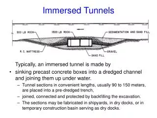
Immersed Tunnels. Typically, an immersed tunnel is made by sinking precast concrete boxes into a dredged channel and joining them up under water. Tunnel sections in convenient lengths, usually 90 to 150 meters, are placed into a pre-dredged trench,

Immersed Tunnels
E N D
Presentation Transcript
Immersed Tunnels Typically, an immersed tunnel is made by • sinkingprecast concrete boxes into a dredged channel and joining them up under water. • Tunnel sections in convenient lengths, usually 90 to 150 meters, are placed into a pre-dredged trench, • joined, connected and protected by backfilling the excavation. • The sections may be fabricated in shipyards, in dry docks, or in temporary construction basin serving as dry docks.
Immersed tunnels are, • more advantegous as a subaquous solution in soft soils • increasingly used alternative to traditionally used shield tunnelling, without having the risks associated with pressure chambers and inrush of water. • also suitable in water deeper than it is possible with the shield method, which essentially is restricted to less than 30 m of water (concerning the maximum air pressure at which workers can safely work). • Advantegous as there is less loss in height than with tunnelling deeply under the riverbed, and the tunnel may therefore be shorter overall.
The world's longest and deepest application to date is the twin-tube subway crossing of San Francisco Bay, constructed between 1966 and 1971 with a length of 3.6 miles (5,8 km) in a maximum water depth of 41 m. The 100 m long, 15 m wide sections were constructed of steel plate and launched by shipbuilding procedures. • The first tunnel of the concrete type was constructed in 1940 in Rotterdam under the Maas estuary.
The most profound effect of an immersed tunnel on the environment concerns the element it is meant to bypass—water. • The influence of the tunnel on the groundwater and the surface water in the area plays a predominant role in the tunnel design and construction methods. • An aspect of more recent concern affecting construction is the possible presence of contaminated soils that must be removed for the tunnel trench. Ways of removing these soils and transporting them to depositories that are especially equipped to receive them are environmental problems requiring novel techniques and quality control procedures. • The more traditional environmental aspects are those encountered on any construction job: noise, dirt, and traffic hindrance.
The top of the tunnel should be protected by adequate protective backfill, extending about 30 m on each side of the structure and confined within dykes or bunds. The fill must be protected against erosion by currents with a rock blanket, protective rock dykes or other means. • Tides and current effects of the waterway must be evaluated to determine conditions during dredging and tube sinking operations. • Importantly, dredging and backfilling operations should be executed in such a manner as to limit disturbance in the natural ecological balance at the construction site. • Governmental agencies having jurisdiction over environmental protection, natural resources or local conditions must be consulted and approval of authorities should be obtained in the preliminary design stage.
Foundation • The foundation method to be used must be chosen with due consideration, first of all, for the subsoil conditions and the degree to which the tunnel will be subject to dynamic loadings, and earthquake loadings in particular. Pile foundations are an option but this solution has been used for a few tunnels only. For both steel and concrete types of tunnels, the main tasks are: • Excavation of a tunnel trench to specifications and to keep it free of siltation that may be detrimental to the permanent foundation until this foundation has been constructed and the tunnel has been brought to rest on it. • Construction of watertight and durable tunnel elements. • Installation of the tunnel elements in the tunnel trench. • Construction of watertight and durable joints between the tunnel elements. • Construction of a durable foundation for the tunnel.
Once completed, an immersed tunnel is no different operationally from any other tunnel. However, it is built in a completely different way. The Construction technique: • A trench is dredged in the bed of the water channel.
Tunnel Trench Dredging The dredging works required for the construction of an immersed tunnel will normally comprise some, or all, of the following items: • Dredging of a casting or launching basin. • Dredging of test pits in the waterway for evaluation of siltation of tunnel trench. • Widening of the existing navigation channel in order to provide temporary navigation channels outside the marine working area. • Compensation grouting to make up for the reduction of the waterway cross section caused by the permanent tunnel works, and thereby avoiding changes in hydrographical and biological conditions in the waterway. • Dredging of the tunnel trench for the immersed tunnel section. • Dredging of an access channel between the casting/launching basin and the tunnel trench. • Maintenance dredging.
The dredging volume is generally in the order of l million m3 per km for a typical four-lane motorway tunnel. The excavation must provide space for the prefabricated tunnel body; the sand or gravel foundation under the body as wells as the protective backfill on the sides and on the top of the tunnel. Because the top of the backfill has to be kept below the existing or future navigation channel profile, a trench bottom level at between 25 and 30 m below Low Water level is quite common. Immersed tunnels in deep or open sea may require specially built dredgers.
Except for cases where very soft subsoil, deemed unsuitable for support of the tunnel, has to be removed and replaced by suitable materials, the general requirements for the dredging of the trench bottom are: • A clean, even surface, as close as possible to the upper acceptable limit in order to avoid the economic consequences of having to fill overdredged areas; • A minimum disturbance of the remaining exposed upper soil layers in the trench bottom, in order to limit the changes in the geotechnical characteristics of the subsoil. The possible physical disturbance and softening of the exposed soil layers in the trench bottom, particularly in cohesive subsoils, can have a considerable influence on the geotechnical behaviour of these soil layers later-and, hence, on the quality of the tunnel support as a whole. This in turn influences the design of the structural tunnel body and, thus, eventually the overall economy. These technical requirements are met by: • Using the proper type of dredger(s). • Careful controlling the position of the cutting tool, bearing in mind that the dredging normally has to be done in tidal waters and sometimes in waters subject to swell and waves. • Careful planning the dredging operation in order to avoid undesirable failures of the slopes. • Timing of the dredging operation, in order to limit the time that the trench bottom is exposed and, at the same time, to limit the sedimentation caused by subsequent dredging nearby.
Construction of Tunnel Elements • The tunnel elements are made fully or partially buoyant by means of temporary bulkheads installed at the element ends. • In addition to providing proper structural strength and controlling the weight of the element, the main design and construction task of the reinforced concrete tunnel is to provide a watertight structure.For many years, the answer was to wrap the tunnel element in a watertight membrane composed of steel on the bottom, outer walls and even on the roof. Alternatively, bituminous membrane has been used on the outer walls and roof. • In recent years, reinforced concrete tunnels without a membrane at all are being used. Above all, this will require sophisticated control of concrete temperature during hardening to avoid cracking. In order to reduce the development of cracks during hardening, primarily in the walls when they are cast after the bottom slab, cooling of the lower part of the walls has been the practice for many years. Insulation of the formwork and careful sequencing of stripping of the forms are also used to control the concrete temperature. • Improved field concrete technology aimed at minimising the development of cracks during hardening, combined with moderate prestressing, seems to be the course to follow.
Tunnel elements are constructed in the dry, for example in a casting basin, a fabrication yard, on a ship-lift platform or in a factory unit.
Casting Basins • The tunnel elements can be prefabricated in a casting basin or in a dry dock. For shorter roadway and railroad tunnels, the elements are normally cast in one batch in a casting basin. A programme for control of concrete density and concrete dimensions is required in order to control the weight and displacement of the tunnel elements. • The typical casting sequence is bottom/walls/roof, but sometimes all at once, in 15-20 m segments. • The tunnel elements can be monolithic, or they can be provided with flexible joints between tunnel segments within the elements. The latter arrangement minimises longitudinal bending moments caused by compression of the subsoil in the permanent stage, but is unsuitable for railway tunnels in soft ground and in seismic regions. • Normally the tunnel elements will be buoyant and need to be ballasted prior to flooding of the casting basin in order to make sure that they remain ‘parked’ until they are to be brought to the immersion location. This ballasting is normally done with water contained in purpose-built ballast tanks inside the tunnel element. Pumps and associated pipelines allow charging and removal of the ballast. A number of lifting eyes and bollards must be provided on the element roof. • Watertight, temporary bulkheads are installed at the ends of the element, and rubber gaskets are mounted around the periphery of the one end of the tunnel element, while a plane steel plate is provided at the opposite end. Later, when the tunnel element is joined to the previously placed tunnel element, this gasket provides a watertight seal between the two tunnel elements. • As the casting basin is flooded or as the tunnel is launched from the dock, the tunnel element is checked for watertightness, the attention being directed principally towards the temporary bulkheads and pipe let-ins. • Recently a system of constructing concrete tubes on floating pontoons is developed. By removing the need for casting basins on theriver or canal costs are reduced, and the process is more environmentally friendly.
The ends of the element are then temporarily sealed with bulkheads. • Each tunnel element is transported to the tunnel site - usually floating, occasionally on a barge, or assisted by cranes.
Installation of tunnel elements in the trench For transportation of the element from the flooded casting basin or dock to the tunnel trench, conventional towage is normally used. The warping, which ends with the tunnel element being moored for immersion, is normally carried out by the contractor's organisation responsible for the subsequent sinking and joining, whereas towing normally is done by experienced towage companies. The immersion of the tunnel element is carried out after the tunnel element bas been moored and the element has been ballasted as necessary to provide adequate loads in the immersion tackles.
The tunnel element is lowered to its final place on the bottom of the dredged trench.
The new element is placed against the previous element under water. Water is then pumped out of the space between the bulkheads. • Water pressure on the free end of the new element compresses the rubber seal between the two elements, closing the joint.
Once placed, the elements are joined; first by bringing rubber gasket at the joint into contact with the steel face of the previously placed tunnel element, and then draining the joint chamber, thereby mobilising the full hydrostatic water pressure on the tunnel cross section remote end.
Backfill material is placed beside and over the tunnel to fill the trench and permanently bury the tunnel, as illustrated in the figures.
Approach structures can be built on the banks before, after or concurrently with the immersed tunnel, to suit local circumstances.
Immersed tunnels have been in widespread use for about 100 years. Over 150 have been constructed all over the world, about 100 of them for road or rail schemes. Others include water supply and electricity cable tunnels. The examples given indicate the diversity of projects that have been realized.
Immersed tunnels do not suit every situation. However, if there is water to cross, they usually present a feasible alternative to bored tunnels at a comparable price, and they offer a number of advantages, such as: • Immersed tunnels do not have to be circular in cross section. Almost any cross section can be accommodated, • making immersed tunnels particularly attractive for wide highways and combined road/rail tunnels. Some examples of realised cross sections are shown below.
Immersed tunnels can be placed immediately beneath a waterway. In contrast, a bored tunnel is usually only stable if its roof is at least its own diameter beneath the water. This allows immersed tunnel approaches to be shorter and/or approach gradients to be flatter - an advantage for all tunnels, but especially so for railways.
expensive, such as the soft alluvial deposits characteristic of large river estuaries. They can also be designed to deal with the forces and movements in earthquake conditions, as in the example illustrated above, to be placed in very soft ground in an area prone to significant earthquake activity.
Bored tunnelling is a continuous process in which any problem in the boring operation threatens delay to the whole project. • Immersed tunnelling creates three operations - dredging, tunnel element construction and tunnel installation, which can take place concurrently, thus moderating programme risk considerably. • Partly for this reason, an immersed tunnel is generally faster to build than a corresponding bored tunnel.
ARE THERE ANY SPECIAL PROBLEMS ? • Immersed tunnels are sometimes perceived by newcomers to the technology as "difficult" due to the presence of marine operations. In reality though, the technique is often less risky than bored tunnelling and construction can be better controlled. The marine operations, though unfamiliar to many, pose no particular difficulties.
The perceived problems include: DREDGING • Dredging technology has improved considerably in recent years, and it is now possible to remove a wide variety of material underwater without adverse effects on the environment of the waterway.
INTERFERENCE WITH NAVIGATION • Interference with navigation: On busy waterways, it is sometimes assumed that construction of an immersed tunnel would be impractical as it would interfere with shipping. In fact, such tunnels have been successfully built in some exceptionally busy waterways without undue problems.
WATERTIGHTNESS • It is often assumed that the process of building a tunnel in water, rather than boring through the ground beneath it will increase the likelihood of leakage. In fact, immersed tunnels are nearly always much drier than bored tunnels, due to the above-ground construction of the elements. Underwater joints depend on robust rubber seals which have proved effective in dozens of tunnels to date.
A NEW DEVELOPMENT: THE SUBMERGED FLOATING TUNNEL • Traditional immersed tunnelling results in a tunnel buried beneath the waterway which it traverses. A new development- the submerged floating tunnel - consists of suspending a tunnel within the waterway, either by tethering a buoyant tunnel section to the bed of the waterway, or by suspending a heavier-than-water tunnel section from pontoons. • This technique has not yet been realised, but one project, in Norway, is currently in the design phase. The submerged floating tunnel allows construction of a tunnel with a shallow alignment in extremely deep water, where alternatives are technically difficult or prohibitively expensive. Likely applications include fjords, deep, narrow sea channels, and deep lakes.
Design Aspects of Immersed Tunnels • The starting point of an immersed tunnel design is required cross-sectional area i.e. the ‘hollow space’. The tunnel must have the same number of traffic lanes as the road. • Dimensional requirements vary from country to country; generally speaking the lanes should be 3,5 m wide with headroom above, depending on local regulations (e.g. 4.5 m for Holland). • There should also be a clearance from the carriageway to the walls of 0.8 to 1.0 m, for broken down cars. The clearance will also reduce the ‘wall effect’; drivers shying away from the wall thereby reducing the capacity of the road. Above the headroom there should be adequate room for ventilation booster fans, luminaries and signal equipment. In the dual-carriageway tunnels there is often a service gallery for cables located between the traffic tubes.
Design for floating • After construction, the elements are floated to their final position. The element is then made heavier than its displacement by means of temporary ballast (often water), after being temporarily supported by the immersion rigs. At a later stage this ballast is replaced by definitive ballast in the shape of non-reinforced concrete below the future carriageway or externally, or other secondary interior structural concrete. By this time the immersion equipment and bulkheads will have to be removed. The element must now weigh sufficiently more than its buoyancy to remain in place. • The pressure head of the groundwater below the tunnel base may lag behind the water level in the river. At low tide this may result in an additional upward force. To compensate for effects of this kind, the design criterion often adopted at this stage is that the weight of the tunnel must exceed the water displacement by an absolute minimum margin against flotation when all removable items and backfill are removed. This floation margin may be in the range of 1.075, but is determined on a project basis. The safety margin is later increased because the sides and top of the dredged trench into which the tunnel was placed is then backfilled. • This results in the first place in a load on the roof; whereas friction on the walls is ignored. Erosion protection is placed to continuously maintain a 1.15 or 1.2 factor of safety against flotation, depending upon the client’s requirements, and safety against sinking ships and dropping anchors.
At the transport stage , Weight = 0.99 · maximum water displacement or 2.46 S + 3.0 = 0.99 (B + H + S) (1) A value of 2.46 will be taken as the specific weight of reinforced concrete in the flotation stage, and a density of 2.42 in the final stage. In the final phase a counter-flotation margin should apply, assume this margin to be 7,5 per cent, hence: Weight = 1.075 water displacement, or 2.42 S + 2.25 B = 1.075 (B + H + S) (2)
Case study: Øresund Link Strait crossing • The Øresund link connects Copenhagen on Zealand, Denmark to Malmö in Sweden thus establishing a land traffic corridor from Scandinavia to the continent. The link comprises a 3.5 km immersed tunnel, 4 km artificial island, and 8 km bridge, including a 490 m span cable-stayed bridge. The link incorporates approximately one million m³ of concrete, of which more than two thirds constitute the immersed tunnel. • The Øresund Tunnel was motivated by the fact that one of the main shipping lane is very close to the Copenhagen international airport, making a high bridge over the nearest navigational channel unfeasible.
The tunnel cross-section accommodates two tubes for the two-track railway and two tubes for the four-lane motorway. A central installation gallery between the motorway tubes doubles as a safe and smoke-free escape route in case of emergency. • The immersed part of the tunnel consists of 20 elements, each approximately 175 m long, resulting in a total immersed tunnel length of 3,510 m. Each element is made from 8 segments, joined together by temporary prestressing, and weighing approximately 56,000 t. The outer cross-sectional dimensions are 8.6 m by 38.8 m, the height being governed by the railway clearance profile. The track is fastened directly to the bottom slab, the omission of the ballast reducing the required tunnel height. The elements were placed in a pre-dredged trench, and founded on a gravel bed. Backfilling along the sides and on the roof was designed to offer a permanent cover and protection of the tunnel in all situations. • The final tunnel profile is in general below seabed level, and at the Drogden navigation channel the top of the cover is 10 m below water level. The rock cover was designed to withstand a falling or dragging anchor, or a sunken ship. Furthermore the protective layer is stable against scour and erosion caused by currents or ship propellers.
All 20 Tunnel elements were fabricated in a purpose-built casting yard. The precast facility applied production techniques developed and tested in the construction of bridges over the last 20 years, but it was the first time these techniques were applied to immersed tunnel construction, involving casting and in incrementally launching segments weighing up to 7,000 t and elements of 56,000 t. • Factory conditions were achieved by the erection of sheds where the reinforcement was assembled and prefabricated. A central shed covered two production lines, where two segments were made simultaneously per week, in order to meet the time schedule. Each 22 m segment was constructed on specially prepared formwork, being cast in one single pour of 2,800 m³ of concrete over a 30-hour period. By casting an entire segment in a single operation production was sped up, and thermal cracking of the concrete was minimized. A crack-free concrete is essential, since the tunnel design does not include a watertight membrane.


![[Lab] 6to4 Tunnels](https://cdn1.slideserve.com/3364996/lab-6to4-tunnels-dt.jpg)