Download
1 / 17
170 likes | 596 Vues
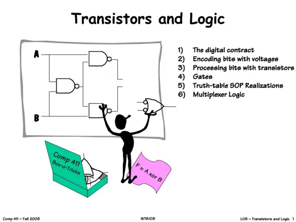
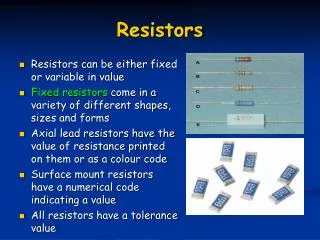
IC Transistors and Resistors. Resistors Bipolar Transistors MOS DMOS. Chris Kendrick Jan. 29, 2003 BiCMOS Design. Resistor Voltage Coefficient. Figure 1 A p type region in an n type tub forms the resistor. http://adev.onsemi.com/knowledge_net/index.html. Resistor Voltage Coefficient.

E N D
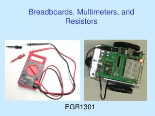
IC Transistors and Resistors • Resistors • Bipolar Transistors • MOS • DMOS Chris Kendrick Jan. 29, 2003 BiCMOS Design
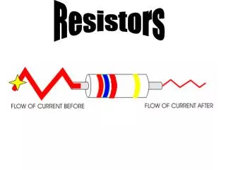
Resistor Voltage Coefficient Figure 1 A p type region in an n type tub forms the resistor. http://adev.onsemi.com/knowledge_net/index.html
Resistor Voltage limits • The maximum resistor voltage is NOT defined by the tub it’s sitting in! • The voltage rating of the tub determines the spacing of PHV to Epi
Lateral PNP Saturation http://adev.onsemi.com/knowledge_net/index.html
C B E FOX FOX PSD PHV NSD Epi PSD PHV PHV PSD Substrate PNP (PHV/Epi - Emitter 21x 21 UDR) cross-section FOX Low current NPN/PNP biasing • What’s the lowest current bipolars can be biased at? Lateral PNP ICmin ~ 5uA
E C C B FOX FOX PWell PSD PHV NSD NHV Epi PHV NSD PSD PSD Substrate PNPV (PSD/NHV - Emitter 28 x 28 UDR) cross-section Low current NPN/PNP biasing • What’s the lowest current bipolars can be biased at? Vertical PNP ICmin ~ 20nA
C E B FOX FOX NSD NSD PHV PHV Epi PSD PSD Substrate NPN (NSD/PWell - Emitter 21 x 21 UDR) cross-section FOX PWell Low current NPN/PNP biasing • What’s the lowest current bipolars can be biased at? NPN ICmin ~ 20nA
S D G Poly BPSG BPSG FOX FOX PWell Epi NSD Substrate Low Voltage NMOS cross-section MOS Safe Operating Area • Hot carrier injection limits NMOS operating voltage
Measured Vds Max (V) Id 10% Device 1 yr. 10 yr. LV NMOS 100x6 5.5 5.1 LV NMOS 100x16 6.8 6.5 LV LVT NMOS 100x6 5.1 4.6 LV LVT NMOS 100x16 6.4 6.1 LV NMOS Hot Carrier Injection • Maximum Vds determined from HCI measurements 10% degradation in 10 yrs • Transient Vds rating based on 10% duty cycle
LV LVT PMOS drain-source leakage • Drain-source leakage determines maximum Vds at high temperature • Minimum channel length targeted based on process variation and independent SEM measurement 150C 27C
Active Area width Active Area length Ex : LDMOS transistor DMOS Specific Rdson Rsp = Rdson x transistor active area transistor active area = # cells x cell area
S G D N+ P+ N+ N+ P+ N+ Sinker PHV PHV PW N-Epi N-Buried Layer P-substrate DMOS Specific Rdson • More components to Rdson than just channel resistance • RCH + REpi + RBL + RMetal • Series resistance causes ‘bend’ in ID vs. VG curve
Device size (cells) R-series (Ohms) Total rdson (OHMs) % series resistance NLDMOS_13V 5x20 0.37 0.69 54 % NLDMOS_30V 5x20 NLDMOS_45V 5x20 1.44 1.99 72 % PLDMOS_13V 5x20 1.25 2.66 47 % PLDMOS_45V 5x20 2.8 5.0 36 % VDMOS_HD 15x46 1.63 1.84 89 % VDMOS_HEC 13x46 A useful way to extract DMOS series resistance (1) (2) Substituting (2) into (3) gives, (3)
DMOS Clamped Inductive Switching • Clamping the flyback voltage below the DMOS breakdown increases energy capability. • Power dissipation eventually allows parasitic bipolar to turn on, killing device