More on VHDL
330 likes | 532 Vues
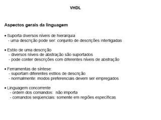
More on VHDL EGR 270 – Fundamentals of Computer Engineering. 1. Reading Assignment: Chapters 4 and 5 in Logic and Computer Design Fundamentals, 4 th Edition by Mano. More on VHDL. VHDL to be explored: Concurrent signal assignments Processes

More on VHDL
E N D
Presentation Transcript
More on VHDL EGR 270 – Fundamentals of Computer Engineering 1 Reading Assignment:Chapters 4 and 5 in Logic and Computer Design Fundamentals, 4th Edition by Mano More on VHDL • VHDL to be explored: • Concurrent signal assignments • Processes • Data Flow, Structural, and Behavioral models • Components • Finite state machines (sequential circuits) • Overview of FPGA labs
More on VHDL EGR 270 – Fundamentals of Computer Engineering 2 Concurrent Signal Assignments • Concurrent signal assignments are evaluated when a signal in their expression changes. • Example: • A <= B and(notCorD); Signal A is updated if any changes occur in signals B, C, or D • Concurrent signal assignments are updated simultaneously and the order in which they are listed doesn’t matter. • Example: • Y1 <= A and B; • Y2 <= A or C; • Y3 <= A xor D; These three statements could be written in any order. Signals Y1, Y2, and Y3 are updated simultaneously if signal A changes
More on VHDL EGR 270 – Fundamentals of Computer Engineering 3 • Three types of concurrent signal assignments: • Simple signal assignment • Example: • Conditional signal assignment • Example: • Selected signal assignment • Example: • A <= B and(notCorD); • A <= B when(X = ‘1’) else C; • withMuxSelselect • Mux4x1 <= • A when “00”, • B when “01”, • C when “10”, • D when “11”, • ‘X’ when others ;
More on VHDL EGR 270 – Fundamentals of Computer Engineering 4 Processes • VHDL includes many common programming language constructs, including decision structures (if, case), looping structures (for, while), functions, arrays, and more. • VHDL examples considered so far have only used concurrent statements. In order to update signals based on more complicated conditions, processes are often used. A process is a sequential section of code that is executed whenever any of the arguments in its sensitivity list change. VHDL code involving higher level constructs is often placed in a process. Name process (sensitivity list) begin VHDL instructions to be executed sequentially end process;
More on VHDL EGR 270 – Fundamentals of Computer Engineering 5 Process Example: 4x1 Multiplexer signal Sel : std_logic_vector(1 downto 0); signal A,B,C,D,Y : std_logic; … Mux_4x1_Proc process (Sel, A, B, C, D) begin case Sel is when “00” => Y <= A; when “01” => Y <= B; when “10” => Y <= C; when “11” => Y <= D; when others => Y <= ‘X’; end case; end process; If Sel, A, B, C, or D change, the sequential process is executed. A 4 x 1 B Y MUX C D S1 S0
signal Addr : std_logic_vector(1 downto 0); signal Decode : std_logic_vector(3 downto 0); … Decoder_2x4_Proc process (Addr) begin case Addr is when “00” => Decode <= “1000” ; when “01” => Decode <= “0100” ; when “10” => Decode <= “0010” ; when “11” => Decode <= “0001” ; when others => Decode <= “XXXX” ; end case; end process; Process Example: 2x4 Decoder 2 X 4 Decoder D0 D1 If Addr changes, the sequential process is executed. A 21 D2 B 20 D3
More on VHDL EGR 270 – Fundamentals of Computer Engineering 7 Process Example: D flip-flop D Q DFF_Proc process (CLK) begin if rising_edge(CLK) Q <= D; end if; end process; CLK If CLK changes, the sequential process is executed. Q
More on VHDL EGR 270 – Fundamentals of Computer Engineering 8 Process Example: D flip-flop with asynchronous Clear DFF_with_CLR_Proc process (CLK, reset) begin if (reset = ‘1’) then Q <= ‘0’; elsif (CLK’eventand CLK = ‘1’) then Q <= D; end if; end process; If CLK or reset changes, the sequential process is executed. D Q CLK Q CLR reset Note: This example and the previous example used two different ways of detecting rising clock edges.
More on VHDL EGR 270 – Fundamentals of Computer Engineering 9 Process Example – three D flip-flops D3reg_Proc process (CLK) begin if rising_edge(CLK) Q1 <= D1; Q2 <= D2; Q3 <= D3; end if; end process; In the last two examples, a process was used to represent a flip-flop (or register). In the example below, the process actually represents three flip-flops (or a 3-bit register). D1 Q1 D2 Q2 D3 Q3 Q1 Q1 Q1 CLK
More on VHDL EGR 270 – Fundamentals of Computer Engineering 10 Concurrent Signal Assignments and Processes Concurrent signal assignments are essentially simplified processes, where all signals in the expression form the sensitivity list. VHDL code can contain many processes and concurrent signal assignments. Y1 <= Aand C; P1 process (A, D) begin …. end process; Y2 <= Aor not C; P2 process (B, D) begin …. end process; Y3 <= not B and not C; P3 process (A, E) begin …. end process; Y4 <= Axor C; • If signal A changes: • Y1, Y2, Y4 are updated • Processes P1 and P3 are run These all occur concurrently!
More on VHDL EGR 270 – Fundamentals of Computer Engineering 11 • Modeling styles within an architecture • VHDL architectures may be described in three manners: • Structural description • Description is based on interconnection of components (to be introduced shortly). Similar to a schematic. We might define components for gates, decoders, adders, etc., and then describe how they are connected. • Works well for simple circuits, but not for huge designs • Is closely related to the hardware in which it will be implemented, so the design is relatively straightforward and easily implemented by the software. • Dataflow description • Outputs are described using signal assignments without specifying the underlying hardware. • Example: f <= ((not A) and B) or (C and D); • Behavioral description • Describes what the system or circuit does, rather than describing the components. • Typically involves the uses of processes. • Allows for the use of more abstract constructs (functions, conditional and iterative structures, etc.) • More powerful for large designs, but requires experience to avoid unrealistic designs.
More on VHDL EGR 270 – Fundamentals of Computer Engineering 12 • Lab 5: Designing a custom 7-segment display decoder • Data Flow Description • In Lab 5 we designed a custom 7-segment display decoder using a data flow description, which means that we simply used signal assignments to assign values to each output. • We determined output Boolean expressions for each segment. • Ex: • Behavioral description • We could have simply described how the circuit should behave (using a process) and let the synthesizer figure out the best way to implement it. • Ex: SegA <= not(C or A or (not B and not D) or (B and D)); • DisplayEncodeProc : process (BCD) • begin • case BCD is • -- Cathode value (active-Low) • -- abcdefg(dp) dp = decimal point • when "0000" => Seg <= "00000011"; -- display digit 0 • when "0001" => Seg <= "10011111"; -- display digit 1 Let’s look at the two approaches on the following slides:
More on VHDL EGR 270 – Fundamentals of Computer Engineering 13 Data Flow Description – use Kmaps to determine Boolean expressions for each output and enter the expressions using signal assignments: This is the method we used in Lab 5
More on VHDL EGR 270 – Fundamentals of Computer Engineering 14 Behavioral Description – describe the output (which segments should light) and let the synthesizer determine how to implement it. This would have been an easier approach for Lab 5 (no Kmaps!) This example also uses standard logic vectors to simplify the process.
More on VHDL EGR 270 – Fundamentals of Computer Engineering 15 Testbenches for 7-segment display – Using standard logic vectors also simplified the testbench. Testbench waveform description without vectors: Testbench waveform description with vectors:
More on VHDL EGR 270 – Fundamentals of Computer Engineering 16 Simulation results without vectors: When ABCD = 0001, decimal digit “1” should be displayed, so only segments b and c should be LOW (segments lit)
More on VHDL EGR 270 – Fundamentals of Computer Engineering 17 Simulation results with vectors: After expanding vector Seg: Recall: Seg(7) = a Seg(6) = b Seg(5) = c Seg(7) = d Seg(7) = e Seg(7) = f Seg(7) = g Seg(0) = dp When ABCD = 0001, decimal digit “1” should be displayed, so only segments b and c should be LOW (segments lit) Note that the BCD input is very easy to read in hexadecimal format
More on VHDL EGR 270 – Fundamentals of Computer Engineering 18 Components in VHDL Components are essentially sub-blocks that describe gates, devices, subsystems, etc. You can create VHDL code for commonly needed components and then creates instances of the components in other VHDL files that would like to use those components. This allows you to create libraries of parts and to break a large design into multiple parts. Example: Suppose that we wanted to model a system that included two flip-flops and a decoder as shown below. D Q 2 X 4 Decoder Out0 CLK A Out1 21 Q D0 B Out2 20 Out3 D Q D1 Q
More on VHDL EGR 270 – Fundamentals of Computer Engineering 19 Components in VHDL - continued Since flip-flops and decoders are devices that we might commonly need, it might be useful to make them components. So we will make three VHDL files in the same project: File: CompleteCircuit.vhd -- VHDL for complete circuit entity … … end … ; architecture of … -- DFF component declaration -- Decode2x4 component declaration … U1: component instantiation (for FF1) U2: component instantiation (for FF2) U3: component instantiation (for decoder) … end … ; File: DFF.vhd -- VHDL for D FF File: Decode2x4.vhd -- VHDL for 2x4 decoder
More on VHDL EGR 270 – Fundamentals of Computer Engineering 20 Components in VHDL – Example: 4x1 mux using components Create a 4x1 mux using three 2x1 muxes. Use a component for a 2x1 mux. Component U1 I(0) Y0 I(1) A A A 2 x 1 2 x 1 2 x 1 Y Y Y MUX MUX MUX B B B Component U3 S S S Y Component U2 I(2) Y1 I(3) Note that two intermediate signals, Y0 and Y1, were added. S(0) S(1)
More on VHDL EGR 270 – Fundamentals of Computer Engineering 21 Components in VHDL – Example: 4x1 mux using components VHDL code for the 2x1 Mux. This will be used as a component of the 4x1 Mux. (But nothing in this file indicates that it might be used as a component. It is just a regular VHDL file.)
More on VHDL EGR 270 – Fundamentals of Computer Engineering 22 Components in VHDL – Example: 4x1 mux using components VHDL code for 4x1 Mux. Note that the VHDL code for 2x1 Mux and the 4x1 Mux are in the same workspace.
More on VHDL EGR 270 – Fundamentals of Computer Engineering 23 Lab #7 • In Lab 7 will involve designing and implementing a custom counter. • Students will design a custom counter using the Finite State Machine (FSM) Wizard in Aldec Active HDL. Details are provided in a tutorial that can be followed in lab. This design might be named Counter.vhd. • The BASYS2 FPGA Board includes a 50 MHz internal clock. The instructor will provide you with VHDL files for: • Dividing the internal clock to produce a 1 Hz clock (ClockDivider.vhd) • BCD to 7-segment decoder (BCD_to_7Segment.vhd) • Main structural file connecting the three components (CounterWithClock.vhd) • See the schematic on the next page. It is important to use a schematic to clearly show how the components are connected and how the signal names relate. Note that intermediate signals often need to be added. • The VHDL code to be provided is also shown on the following slides and is also available on the course Bb site.
Lab #7 CounterWithClock.vhd Component U2 Component U1 CLK50M clkin Counter.vhd Custom Counter ClockDivider.vhd Clock Divider clkout CLK1 CLK reset reset X UpDown A (MSB) C B B(0) B(1) to BASYS2 pins B(2) Component U3 BCD(3) B(3)=‘1’ Seg(6:0) BCD_to_7Segment.vhd BCD to 7-segment Decoder BCD(2) BCD(1) BCD(0) An(3:0) Intermediate signals (in green) to be added in CounterWithClock.vhd Seg(6:0) To BASYS2 pins An(3:0)
Lab #6: Breadboard 555 Timer, R’s, C’s 1 Hz Clock JK Flip-flops, logic gates Custom Counter 7447 BCD to 7-segment Decoder Lab 7: Spartan 3E FPGA on BASYS2 board BASYS2 Internal 50 MHz Clock BCD_to_7Segment.vhd BCD to 7-segment Decoder Counter.vhd Custom Counter ClockDivider.vhd Clock Divider BASYS2 7-segment display 25