VHDL Advantages
VHDL Advantages. Modular Hierarchical , Allows Design Description : TOP - DOWN, BOTTOM - UP, Portable Can Describe the Same Design Entity using More than one View (Domain): The Behavioral View ( e.g. as an algorithm, Register-Transfer (Data Flow), Input-Output Relations, etc)

VHDL Advantages
E N D
Presentation Transcript
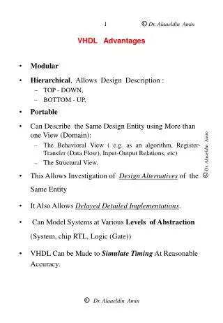
VHDL Advantages • Modular • Hierarchical, Allows Design Description : • TOP - DOWN, • BOTTOM - UP, • Portable • Can Describe the Same Design Entity using More than one View (Domain): • The Behavioral View ( e.g. as an algorithm, Register-Transfer (Data Flow), Input-Output Relations, etc) • The Structural View. • This Allows Investigation of Design Alternatives of the Same Entity • It Also Allows Delayed Detailed Implementations. • Can Model Systems at Various Levels of Abstraction (System, chip RTL, Logic (Gate)) • VHDL Can be Made to Simulate Timing At Reasonable Accuracy.
DESIGN ENTITY Basic Modeling Unit • Interface Specs • Name • Ports (In, Out, InOut) • Attributes • Architectural Specs • Behavioral(Algorithmic , DataFlow) • Structural ICON A Name Z B Hardware MOdeling using vhdl • VHDL is NOTCaSe-SeNsItIvE, Thus: Begin = begin = beGiN • Semicolon “ ;” Terminates Declarations or Statements. • Line Feeds and Carriage Returns are not Significant in VHDL.
A0 C0 A1 C1 A2 ONES_CNT C1 Majority Fun C0 Function AND2 OR3 AND3 OR4 Example“Ones Count CIRCUIT” • Value of C1 C0 = No. of Ones in the Inputs A2, A1, and A0 • C1 is the Majority Function (=1 IFF Two or More Inputs =1) • C0 is a 3-Bit Odd-Parity Function (OPAR3)) • C1 = A1 A0 + A2 A0 + A2 A1 • C0 = A2 A1’ A0’ + A2’ A1’ A0 + A2 A1 A0 + A2’ A1 A0’
1 2 DOCUMENTATION 3 Example “Ones Count CIRCUITINTERFACE SPecs entityONES_CNT is port ( A : in BIT_VECTOR(2 downto 0); C : out BIT_VECTOR(1 downto 0)); -- Function Documentation of ONES_CNT -- (Truth Table Form) -- --------------------------------------------------- -- This is a COMMENT -- ___________________ -- | A2 A1 A0 | C1 C0 | -- |----------------|------------| -- | 0 0 0 | 0 0 | -- | 0 0 1 | 0 1 | -- | 0 1 0 | 0 1 | -- | 0 1 1 | 1 0 | -- | 1 0 0 | 0 1 | -- | 1 0 1 | 1 0 | -- | 1 1 0 | 1 0 | -- | 1 1 1 | 1 1 | -- |__________ |________| -- endONES_CNT;
example “Ones Count CIRCUITArchitectural Body((((( Behavioral view-1 ))))) architectureAlgorithmic of ONES_CNTis begin Process(A) -- Sensitivity List Contains only Vector A Variable num: INTEGER range 0 to 3; begin num :=0; For i in 0 to 2 Loop IF A(i) = '1' then num := num+1; end if; end Loop; -- -- Transfer "num" Variable Value to a SIGNAL -- CASE num is WHEN 0 => C <= "00"; WHEN 1 => C <= "01"; WHEN 2 => C <= "10"; WHEN 3 => C <= "11"; end CASE; -- end process; endAlgorithmic;
example “Ones Count CIRCUITArchitectural Body ( Behavioral (Data Flow) view - 2 ) architectureTwo_Level ofONES_CNTis begin C(1) <=(A(1) and A(0)) or (A(2) and A(0)) or (A(2) and A(1)); -- C(0) <= (A(2) and not A(1) and not A(0)) or (not A(2) and not A(1) and A(0)) or (A(2) and A(1) and A(0)) or (not A(2) and A(1) and not A(0)); endTwo_Level; • C1 = A1 A0 + A2 A0 + A2 A1 • C0 = A2 A1’ A0’ + A2’ A1’ A0 + A2 A1 A0 + • A2’ A1 A0’
Example “Ones Count CIRCUITArchitectural Body ( Behavioral (Data Flow) view - 3 )Using Functions architecture Macro ofONES_CNTis begin C(1) <= MAJ3(A); -- C(0) <= OPAR3(A); endMacro ; • Functions OPAR3 and MAJ3 Must Have Been Declared and Defined Previously
example “Ones Count CIRCUITArchitectural Body((((( Behavioral view -4 ))))) architectureTruth_Table ofONES_CNT is begin -- Process(A) -- Sensitivity List Contains only Vector A Variable num: BIT_VECTOR(2 downto 0); begin num :=A; CASE num is WHEN "000" => C <= "00"; WHEN "001" => C <= "01"; WHEN "010" => C <= "01"; WHEN "011" => C <= "10"; WHEN "100" => C <= "01"; WHEN "101" => C <= "10"; WHEN "110" => C <= "10"; WHEN "111" => C <= "11"; end CASE; -- end process; endTruth_Table;
ONES_CNT C0 Odd-Parity Fun C1 Majority Fun AND2 OR3 AND3 OR4 “Ones Count CIRCUIT example ” VHDL STRUCTURAL DESCRIPTION • C1 = A1 A0 + A2 A0 + A2 A1 =MAJ3(A) • C0 = A2 A1’ A0’ + A2’ A1’ A0 + A2 A1 A0 + A2’ A1 A0’ = OPAR3(A) Structural Design Hierarchy entityMAJ3is PORT( X: in BIT_Vector(2 downto 0); Z: out BIT); end MAJ3; entityOPAR3is PORT( X: in BIT_Vector(2 downto 0); Z: out BIT); endOPAR3;
Maj3 Majority Function VHDL STRUCTURAL DESCRIPTION architecture Structural ofMAJ3is COMPONENT AND2 PORT( I1, I2: in BIT; Declare Components O: out BIT); To Be Instantiated END COMPONENT; COMPONENT OR3 PORT( I1, I2, I3: in BIT; O: out BIT); END COMPONENT; -- SIGNAL A1, A2, A3: BIT; Declare Maj3 Local Signals begin -- Instantiate Gates g1: AND2 PORT MAP (X(0), X(1), A1); g2: AND2 PORT MAP (X(0), X(2), A2); Wiring of g3: AND2 PORT MAP (X(1), X(2), A3); Maj3 g4: OR3 PORT MAP (A1, A2, A3, Z); Compts. end Structural;
entityOPAR3is PORT( X: in BIT_Vector(2 downto 0); Interface Specs Z: out BIT); endOPAR3; -- architecture Structural ofOPAR3is COMPONENTINV PORT(Ipt: in BIT; Opt: out BIT); END COMPONENT; COMPONENTNAND3 PORT( I1, I2, I3: in BIT; O: out BIT); END COMPONENT; COMPONENTNAND4 PORT( I1, I2, I3, I4: in BIT; O: out BIT); END COMPONENT; -- SIGNAL A1B, A2B, A0B, Z1, Z2, Z3, Z4: BIT; Architecture begin Body -- Instantiate Gates g1: INV PORT MAP (X(0), A0B); g2: INV PORT MAP (X(1), A1B); g3: INV PORT MAP (X(2), A2B); g4: NAND3 PORT MAP (X(2), A1B, A0B, Z1); g5: NAND3 PORT MAP (X(0), A1B, A2B, Z2); g6: NAND3 PORT MAP (X(0), X(1), X(2), Z3); g7: NAND3 PORT MAP (X(1), A2B, A0B, Z4); g8: NAND4 PORT MAP (Z1, Z2, Z3, Z4, Z); end Structural;
g8 C0 Odd-Parity (OPAR3) architecture Structural ofOPAR3is Component INV PORT( Ipt: in BIT; Opt: out BIT); end Component ; Component NAND3 PORT( I1, I2, I3: in BIT; O: out BIT); end Component ; Component NAND4 PORT( I1, I2, I3, I4: in BIT; O: out BIT); end Component ; -- SIGNAL A1B, A2B, A0B, Z1, Z2, Z3, Z4: BIT; begin g1: INV PORT MAP (X(0), A0B); g2: INV PORT MAP (X(1), A1B); g3: INV PORT MAP (X(2), A2B); g4: NAND3 PORT MAP (X(2), A1B, A0B, Z1); g5: NAND3 PORT MAP (X(0), A1B, A2B, Z2); g6: NAND3 PORT MAP (X(0), X(1), X(2), Z3); g7: NAND3 PORT MAP (X(1), A2B, A0B, Z4); g8: NAND4 PORT MAP (Z1, Z2, Z3, Z4, Z); end Structural;
Top Structural level of ones_cnt architecture Structural ofONES_CNT is COMPONENTMAJ3 PORT( X: in BIT_Vector(0 to 2); Z: out BIT); END COMPONENT; COMPONENTOPAR3 PORT( X: in BIT_Vector(0 to 2); Z: out BIT); END COMPONENT; -- begin -- Instantiate Components -- c1: MAJ3 PORT MAP (A, C(1)); c2: OPAR3 PORT MAP (A, C(0)); end Structural;
Similarly Other Lower Level Gates Are Defined Behavioral definition of lower level components entityINVis PORT( Ipt: in BIT; Opt: out BIT); endINV; -- architecture behavior ofINVis begin Opt <= not Ipt; end behavior; entityNAND2is PORT( I1, I2: in BIT; O: out BIT); endNAND2; -- architecture behavior of NAND2is begin O <= not (I1 and I2); end behavior;