Download

1 / 13
130 likes | 221 Vues
Learn how to solve complex pipe network problems using the Hardy-Cross Method. Understand the use of node and loop equations, Darcy's Formula, resistance coefficients, and continuity principles. Follow step-by-step instructions for flow distribution and accuracy evaluation.

E N D
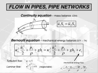
7 Networks of Pipes multiple “inlets” and “outlets.” use of node and loop equations
BC AG D F E ∑hf = 0 , Qin = Qout , Darcy’s Formula or eqv. for hf
Steps of solution:Hardy Cross Method • Assume best distribution of flow that satisfies the continuity • Compute hf = rQonin each pipe • Compute for each circuit • Evaluate • Compute Qrevised = Q +ΔQ • Repeat steps 1) – 5) beginning with revised Q until desired accuracy is obtained.(ΔQ<± 1) • r= RL/Dm; L is length of pipe and D is inside diameter in SI units. • R= 10.675/Cn ; R is resistance coefficient, n = 1.852 ≈2 and m = 4.8704 ≈5
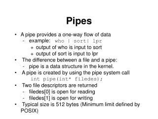
50 20 A r=5 B r=2 r=1ΔQ2 r=1 7035 35 ΔQ1 Dr=4C 30 30 100 hf = rQon Qrevised = Q +ΔQ Example 1: 15
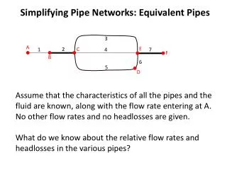
For the left side circuit ΔQ1can be estimated as follows: • A • r=1 • r=2 35 • 70 ΔQ1 • r=4 C • D 30 30 • 100 ΔQ1=
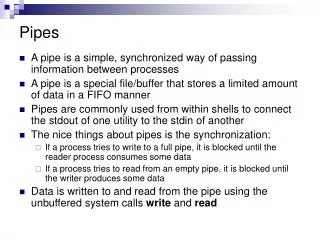
For the right side circuit ΔQ2 can be estimated as follows: 20 15 50 A r=5 B r=1 r=1 35 ΔQ2 35 30 C ΔQ2=
Hence the corrected flows in the individual pipes are: • ΔQ is added to Q in the clockwise flow • ΔQ is subtracted in the anticlockwise flow
Repeating the same steps to calculate ΔQ1 and ΔQ2: • A • r=1 • r=2 17 • 57 ΔQ1 • r=4 C • D 43 30 • 100 ΔQ1=
20 20 50 A r=5 B r=1 r=1 17 ΔQ2 30 30 C ΔQ2=
Hence the corrected flows in the individual pipes are: • ΔQ is added to Q in the clockwise flow • ΔQ is subtracted in the anticlockwise flow
Repeating the same steps to calculate ΔQ1 and ΔQ2: 20 A 17 B 50 r=5 r=2r=121ΔQ2 r=1 58 ΔQ1 33 100 D 42 C 30 r=4 ΔQ1= ≈0 ΔQ2=
Example 2: 3255 3 4 16 1316 ΔQ1 ΔQ2 4 10 4 2 3 2000’ , 8’’, 0.02 1500’, 6’’, 0.018 5 1000’ 600’ 1200’ 4’’, 0.02 6’’, 0.016 4’’, 0.016 3000, 6’, 0.015 10 2 n = 1.85